Themba & Sandile

BCL’s first majority black-owned facility to blend and distribute global brand

Themba & Sandile

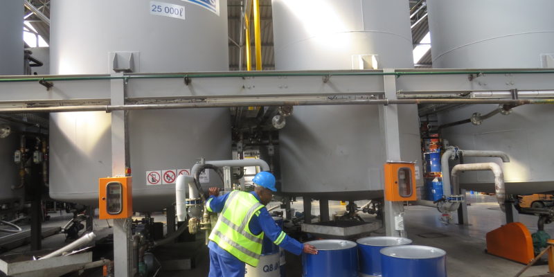
Blue Chip Lubricants has completed construction of its new blending facility in Kya Sands in Johannesburg, South Africa, and is ready to embark on a largescale blending of lubricants from Q8Oils for the South African and Sub-Saharan African market.

The company will have a major presence at Futuroad 2017 at Nasrec, part of Automechanika South Africa, Sub-Saharan Africa’s leading event for the truck and bus industry. Senior management from Q8Oils, Blue Chip Lubricants, and its new equity partners will host a media event on 28 September to announce the finalization of a major Broad-Based Black Economic Empowerment (B-BBEE) transaction that will give the company Level 1 accreditation.

Blue Chip Lubricants secured an agreement to blend and distribute lubricants from Q8Oils in 2015. Following the agreement, it secured funding from the Industrial Development Corporation (IDC) to construct a new state-of-the-art blending facility and testing laboratory at Kya Sands in Johannesburg.

Q8Oils is part of the Kuwait Petroleum Corporation (KPC), one of the world’s largest oil companies. With 120 years of known reserves and crude oil production levels of 2.9-million barrels per day, it is ranked the seventh largest oil producer in the world. KPC’s business spans every segment of the hydrocarbon industry: on and offshore exploration, production, refining, marketing, retailing, petrochemicals and marine transportation.

“The successful conclusion of our B-BBEE transaction effectively makes us the only majority black-owned blending facility in South Africa to blend and distribute a global brand, as well as complying fully with the government’s empowerment, employment, and equity objectives,” Blue Chip Lubricants Director Kathleen Marais comments.

“With lubricants constituting the major expense for equipment-intensive industries such as mining and engineering, the fact that an international brand is now being blended locally on a large scale, in accordance with exacting international quality standards, as well as all local B-

BBEE criteria, is of immense benefit for local companies,” says Lutramart Director, Sandile Koza, who is one of the new B-BBEE partners.

“We are very excited, as we now have the opportunity to rationalize the entire value chain in the petrochemical industry, from blending and manufacture through to proactive maintenance and leveraging the lowest total cost of ownership for our customers. Not only is Blue Chip Lubricants now positioned strategically as a leading lubricant supplier, it has set a benchmark for the proactive transformation of the industry.”

With all of Q8Oils’ infrastructure concentrated in Europe, having a blending facility located strategically in South Africa effectively gives Q8Oils a gateway into the larger Sub-Saharan African market, which represents an untapped region for the oil giant’s future expansion plans.

Blue Chip Lubricants’ also aims to investigate the local manufacture of more specialized products presently imported at premium prices. It plans to engage with major OEMs represented in South Africa in order to secure the necessary approvals to become a preferred supplier to these international companies.

“This will develop our product range even further, as well as assist us in contributing actively to the government’s localization, employment, and skills development criteria in terms of its empowerment objectives,” Marais elaborates.

The B-BBEE agreement is the latest milestone in the evolution of Blue Chip Lubricants, established in 1983 as a mainly grease and oil supplier to the South African mining sector. With a plethora of smaller blenders fragmenting the total market and diluting its overall standards, the company saw an opportunity to establish its own high-quality blending facility, which allowed it to diversify successfully into other industries and markets.

“Our extensive product range includes specialized and general-purpose greases, automotive and industrial oils, cleaning and cutting fluids, and various complementary products such as grease pumps, rags, hand cleaners and degreasers,” Marais highlights. The Q8Oils lubricants range is supported by a team of technical experts.

“Here we offer products to increase operational efficiency by optimising production processes and reducing lubricant consumption. These products have all mandatory OEM approvals, and consistently meet, or exceed, the highest technical requirements and specifications of the industry,” Marais concludes

Link: http://transformsa.co.za/2017/10/bluechiplubricantsfirstmajorityblackownedfacilitytoblendanddistributeglobalbrand/

Brake fluid

Brake fluid OilChat#27

Brake fluid

The brake system is possibly the most neglected component of motorcars. Most drivers check tyre pressures and change engine oil at frequent intervals, but very few motorists replace the brake fluid in their car regularly. If you don’t change your engine oil the worst that can happen, is the engine may seize and your car will come to a standstill. On the contrary, if something goes wrong with the brake system, the car will not stop – with possible catastrophic consequences!

The prime function of brake fluid is to provide a hydraulic medium with a low level of compressibility, to transmit the driver’s foot pressure on the brake pedal to the brakes. Many automotive hydraulic brake systems in use today utilize front disk brakes and drums at the rear, but four wheel disk systems are also fairly common. When braking, the kinetic energy (energy of motion) of the vehicle is converted into heat in the brakes as the vehicle slows down.  A tremendous amount of heat is generated to stop a vehicle from even a modest speed, particularly in disc brakes. The brake fluid is in close contact with the brakes and this can lead to overheated brake fluid.

Overheated brake fluid can boil in the brake lines. Boiling produces vapour (gas bubbles) within the brake fluid. Vapour is compressible and boiling brake fluid leads to a “spongy” brake pedal with long travel. In extreme cases overheated brake fluid requires that the brake pedal be “pumped’ (if you are fortunate enough to have time to do so) in order to get the brakes to respond. This necessitates a closer look at the boiling point of brake fluid.

Most brake fluids used today are glycol-ether based, but silicone type fluids are also available. Brake fluids must meet certain requirements as defined by various institutions. These include the Society of Automotive Engineers (SAE) J1704 standard and the US Department of Transport (DOT) FMVSS 116 specifications DOT 3, DOT 4 and DOT 5.1 (glycol-ether based) and DOT 5 (silicon based). All specifications include minimum boiling points for brake fluid.

Using glycol-ether fluids is the most economical way to meet brake fluid requirements and they are almost incompressible. Glycol-ether, however, is hygroscopic which means it absorbs moisture from the atmosphere. These brake fluids start to absorb moisture from the moment they are put into the hydraulic brake system or exposed to the atmosphere. The fluid attracts moisture through microscopic pores in rubber hoses, past leaking seals and exposure to air in the brake fluid reservoir. The problem is obviously worse in wet climates where humidity is high. Moisture reduces the boiling point of the fluid significantly. Minimum boiling point limits are therefore specified for new (dry) brake fluid, as well as fluid contaminated with moisture (wet brake fluid). Wet Boiling Point is defined as the temperature brake fluid will begin to boil after it has absorbed 3.7% water by volume. Silicone fluids are non-hygroscopic which means they can maintain a higher boiling point over the service life of the fluid. A disadvantage of silicone is that it is more compressible than glycol based fluids, resulting in a “soft” brake pedal with longer travel. The differences in the boiling points of the various brake fluid specifications are listed in the table below:


FMVSS 116 Dry Boiling Point Wet Boiling Point
Specification (minimum) (minimum)
DOT 3 205 °C 140 °C
DOT 4 230 °C 155 °C
DOT 5 260 °C 180 °C
DOT 5.1 260 °C 180 °C

DOT 5.1 glycol-ether based brake fluid has been developed to be identical to DOT 5 silicone based fluid in boiling points but without the ‘compressibility’ of silicon fluids. Brake fluids with different DOT ratings cannot always be mixed. It must be of the same type, and at least the same or higher rating. DOT 5.1 can, therefore, replace DOT 4

and DOT 3. Likewise, DOT 4 can replace DOT 3 but not vice versa. Never mix DOT 5 silicon based brake fluid with regular glycol based fluids. None of these should be mixed with DOT 5 as the mixing of glycol and silicone fluids may lead to brake failure.

The boiling points in the table above are minimum specifications and therefore you may well find DOT 4 brake fluids with boiling points above that of DOT 5 and DOT 5.1 specifications. Today DOT 4 is the most commonly used brake fluid and the dry boiling point of most of these fluids exceeds 260°C.  The effect of water content on boiling point over time is illustrated by the graph below. The graph (by courtesy of Shell) demonstrates the declining effect water content has on the boiling point of a typical DOT 3 (red curve) and three DOT 4 brake fluids:


                                          oilchat27

The Impact of Water Content on the Boiling Point of Brake Fluid


We mentioned earlier that DOT specifies the minimum wet boiling point of brake fluid after absorbing 3.7% water. On average this occurs after two years in service. The graph illustrates that in most instances warning limits are reached within this period. It is therefore little wonder that most vehicle manufacturers recommend that brake fluid should be changed every eighteen to twenty-four months. The graph also shows that the boiling points of the various brake fluids decline even further over extended periods of time. When the DOT 3 brake fluid reaches 8% water content the boiling point is reduced almost to that of water!

Brake fluid is crucial to the safe operation of your vehicle. Check your owner’s manual for the recommended brake fluid replacement schedule and brake fluid type. Remember, brake fluid is what is between your brake pedal and the brakes at the wheels. Make brake fluid part of your regular maintenance routine, and replace the brake fluid when necessary to keep you and your passengers safe.

It is also important to remember that brake fluid is toxic and combustible and can damage the paintwork of your vehicle.

Hayley Arnesen

BCL gets a new Sales and Marketing Director

Hayley Arnesen

We are very pleased to welcome Hayley Arnesen into the Blue Chip Lubricants family as our new Sales and Marketing Director.

Hayley started off her career as an English teacher after obtaining her Bachelor of Arts in Education from Wits University. After three years in the field of education she joined the corporate world. Her career has since been on an onward surge, acquiring titles such as Senior Product Manager, Marketing Manager, Marketing Director, Exports Manager, Exports & Customer Loyalty Director and now Sales & Marketing Director for Blue Chip Lubricants.

After two years of working for Discovery Health and was part of the Corporate Relations team she joined MSA, a NYSE listed global leader in the manufacturing and distribution of predominantly, more technical personal protective equipment.  During her 15 years at MSA Hayley was promoted several times and was fortunate to have filled many diverse roles.  During her time she headed up the marketing team, led the company’s expansion into Sub-Saharan Africa, pioneered the customer loyalty program for Africa and Latin America and served on global steering teams for product development.


She always had a passion for the safety industry as a whole and was an exco member of SAPEMA (Southern African Protective Equipment Marketers Association) for 6 years, from 2011 to 2013 she served as the first female Chairman of the association.

Some of her other achievements include working with the mining community to execute the successful South African launch of the internationally renowned safety award, the ‘JT Ryan Award’.

For the last 3 years, Hayley has been part of the dynamic and entrepreneurial team at North Safety Products.  She was successful in the expansion of North Safety’s vast product and services range into Africa by developing and supporting a branch network and larger mining clients.

Hayley joined Blue Chip Lubricants in July 2017, her range of experience in both the Marketing and Sales areas will stand her in good stead for her new exciting role, and we look forward to the wonderful things she will bring to the firm.

Oil splash

The journey of oil in the engine OilChat#26

Oil splash

We have all seen bright and clear fresh oil being poured into an engine when a vehicle is serviced or when the oil is topped up between services. At the next oil change, this same oil is drained looking dirty and contaminated, much darker in colour and with a pungent odour. What we don’t see is what happens to the oil inside the engine in between the two oil services.

When oil is poured into an engine it settles in the oil pan, also known as the sump, at the bottom of the engine. The oil journey begins when the engine is started and the oil is drawn up through the pickup screen and tube by the oil pump. The pump then directs the oil to the oil filter to be cleaned. From the filter, the oil makes its way through the main oil gallery in the cylinder block, to the crankshaft main bearings. It then flows through oil passages (small drilled holes) in the crankshaft to lubricate the piston connecting Oil pump rod bearings. Another oil passage in the block sends oil to the top of the engine to lubricate the valve drive train, including the camshaft Pickup bearings, cam lobes, valve lifters and the valve stems. Once pumped through the engine the oil returns to the oil pan via gravity.

oil2
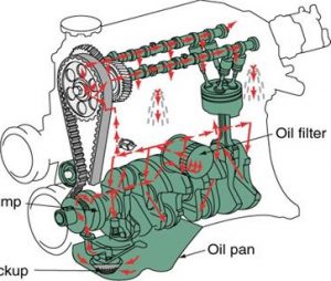
In some engines oil returning to the sump, drips on the rotating crankshaft and is thrown around to lubricate the pistons, rings and cylinder walls. In other designs, small holes are drilled through the piston connecting rods to spray oil on the pistons and cylinder walls.

You may well wonder why the oil is dark and dirty when it is drained at the next service. Manufacturing modern engine oil is a precision operation. Painstaking effort is required to produce oils that will meet the demanding requirements of modern engine manufacturers. When new oil is poured from its sealed container into an engine, it goes from the controlled environment of the oil manufacturing plant into a completely uncontrolled chemical factory – the engine itself. Inside the engine the oil comes into contact with various harmful contaminants:

Water: For every litre of fuel burnt in the engine, about one litre of water is formed in the combustion chamber. At operating temperature this is not a problem since the water goes out the exhaust in vapour form (steam). When the engine is cold, however, some of the water goes past the piston rings into the oil sump. Water is one of the most destructive contaminants in lubricants. It attacks additives, causes rust and corrosion, induces base oil oxidation and reduces oil film strength.

Fuel: At start-up some of the atomised fuel comes into contact with the cold cylinder walls, condenses and find its way into the oil pan where it dilutes the oil. On the way down the fuel causes wash-down of the oil on the cylinder walls and accelerates ring, piston and cylinder wear. Fuel dilution also results in a premature loss of oil base number (loss of corrosion protection), deposit formation and degradation of the oil.

Soot: It is a by-product of combustion and exists in all in-service engine oils, diesel engine motor oil in particular. It reaches the engine oil by various means such as piston blow-by and the scraping action of the oil rings.

Whilst the presence of soot is normal in used engine oil, high concentrations of soot will lead to viscosity increase, sludge, engine deposits and increased wear. Soot is also the major contributor to oil darkening.

Dust: The ingestion of hard abrasive particles into an engine leads to rapid wear of engine components. These particles come in multiple forms including dust/sand, which consists of Silica. Normally the air filter will remove most of the dust from the air going into an engine. However, incorrect air filter maintenance and a leaking air intake system will introduce dust into the engine. Silica is much harder than engine components and less than 1 00 grams of dust can severely affect expected engine life.

Wear Metals: These contaminants are generated inside the engine by the wear of mechanical components. The wear debris is in the form of hard metal particles and abrasive metal oxides. Wear metal particles of sizes smaller than that controlled by standard filtration may well build up to grossly contaminate the oil. These contaminants can wear moving parts as well as clog oil flow passages and heat exchange surfaces. If wear debris accumulates in the oil, the result is more wear, generating more contaminants.

This process is known as the chain-reaction-of-wear. In addition, certain wear metals, such as copper, act as catalysts to promote oil oxidation. oil 3

To make things even worse, the oil comes into contact with high temperatures during its journey through the engine, temperatures in excess of 600 degree Celsius. The effect of elevated temperatures is oil oxidation, also called Black Death. Oxidation causes the oil to darken and break down to form varnish, sludge, sedimentation, and acids. The acids are corrosive to metals in the engine and the sludge can increase the viscosity of the oil, causing it to thicken. It can also increase wear and plug filters and oil passages resulting in oil starvation. In addition, oxidation is a major cause for additive depletion, base oil breakdown, loss in resistance to foaming, acid number increase, and corrosion. The good news is that modern, premium performance engine oils are formulated to withstand high temperatures and oxidation much better than oils from the past. It is therefore important to use a high-quality motor oil that meets the requirements specified by the engine manufacturer.

In conclusion, we need to slot in an important comment about oil change periods, which are directly dependent on lubricant life. Oils are primarily changed to get rid of all these harmful contaminants. It is also essential to fit a new oil filter with every lube service. Dirty or clogged filters allow contaminants to flow straight to your engine where they are responsible for the damages discussed above, as well as affecting fuel economy. You also risk blocking the flow of oil to your engine, which will result in engine failure. Finally, wear metals trapped in the old oil filter will promote early oxidation of the new oil.

Don’t become a victim of Black Death — change your engine oil sooner rather than later, make sure the oil conforms to the specifications recommended by the engine manufacturer and fit a new good quality filter. If in doubt, phone us on 01 1 964 1829 to ensure you are using the correct lubricants for your vehicle or equipment.

Engine

Antifreeze engine coolants OilChat#25

Engine

Research has indicated that up to 60% of all engine failures are related to the engine cooling system and ultimately to the engine coolant being used. Despite this, many vehicle owners use the cheapest coolant available and at the lowest possible concentration.

While oil may be the lifeblood of a vehicle’s engine, no engine (bar the odd air-cooled engine still around) can operate effectively and reliably without a suitable coolant. To appreciate the significance of engine coolants we need to understand their functions in engine cooling systems:

  • They need to be effective heat exchange fluids. The primary function of a coolant is to cool the engine by transferring heat away from internal engine surfaces to the cooling system.
  • Coolants have to provide corrosion protection. They must protect all the materials in the cooling system from degradation due to interaction with the hostile environment present in the cooling system.
  • They should protect against freezing (hence the name antifreeze). Water expands when it freezes which may well result in cracked engine blocks.
  • Engine coolants must prevent boiling. Boiling can lead to overheating as a saturated boiling regime (steam) is very inefficient at transferring heat. Boiling will also cause additional (vapor phase) corrosion.


An ideal antifreeze engine coolant is a mixture of pure water and a high-quality coolant concentrate from a reputable supplier. The recommended concentration is 50% coolant concentrate and 50% water. Water is added since it is an effective heat transfer medium. A typical coolant concentrate is a blend of ethylene glycol, normally between 88% and 96%, and the balance is made up of rust and corrosion inhibitors, lubricity agents and foam inhibitors. Dyes are also added in minute quantities to indicate the presence of the concentrate in the cooling system. While these additives make up only a small fraction of the overall coolant, they are most instrumental in differentiating one coolant from another.

Traditional coolants (based on inorganic chemistry) provide protection against rust and corrosion by forming a protective layer of inhibitor salts on metal surfaces inside the engine that is in contact with the coolant (see Figure. 1 below). While this layer provides protection, it continuously consumes active ingredients (corrosion inhibitors) from the coolant to build and retain the protective layer. These inhibitors, once used, are no longer available to provide further protection. For this very reason, the maximum service interval for traditional coolant concentrates is two years when mixed with 50% water. Another disadvantage of traditional coolants is that the protective layer restricts the heat flow from the metal surfaces to the coolant.

Asset 1

In contrast to traditional coolants, organic acid based coolants provide protection only where it is needed, i.e. where the corrosion actually takes place (Figure 2). As such it is targeted protection. It will effectively stop

corrosion from progressing, but at the same time corrosion inhibitor consumption is minimal and the majority of the surfaces in contact with the coolant remain unaffected. This results in:

  • Unrestricted heat transfer across the metal/liquid interface.
  • Longer coolant service life (hence the term long life coolant).


High quality engine coolants based on organic acid technology (OAT) may be used for periods up to five years when the concentrate is mixed 50/50 with water.


OAT long life engine coolants must not be mixed with traditional coolants since they incorporate different inhibitor chemistries. Not only will the two coolants dilute each other, they can also react chemically to form a gel rather than a liquid. The coolant then stops flowing through the system, clogs up coolant passages, water jackets, radiators, and heater cores. The water pump overheats and fails due to starvation of the lubricity agent in the coolant. Head gaskets blow, heads warp, and the engine suffers major damage. If mixing occurs, it is best to have the entire system flushed. This is the only way to be sure that the system is clean and not at risk. Failure to flush the system can, and often does, lead to engine failure and costly repairs.


Although the preferred dilution ratio for coolants (traditional and OAT) is 50% coolant concentrate and 50% water, they are sometimes used at lower treat rates of the concentrate. In such instances the service intervals mentioned above should be reduced accordingly. The coolant concentrate, however, should not be used at mixing ratios of less than 30%. At such low dosages the coolant will not provide adequate corrosion protection of the engine metal surfaces in contact with the coolant.


Hard water is a serious problem in many parts of southern Africa and reduces the performance of antifreeze coolants, traditional coolants in particular. The minerals found in hard water, react with the (inorganic) inhibitors to form calcium or magnesium phosphate, which leads to scale formation on hot engine surfaces. This can result in loss of heat transfer or corrosion under the scale. To assist vehicle and equipment operators with this problem, many coolant manufacturers market pre-diluted coolants mixed 50/50 with pure high quality water. This also ensures that the correct ratio of concentrate and water is always being used.


Antifreeze engine coolants can be dyed any colour, but traditional coolants are generally blue/green in colour.  Long life coolants are usually dyed orange/red. However, the aftermarket is loaded with high and low-quality coolants of all colours of the rainbow. Colour is therefore not a good indicator of the type and quality of a coolant. Although many consumers use price as the deciding factor when purchasing antifreeze engine coolants, it should be remembered that you only get what you pay for. Some of the low-priced coolants available in the market are not much more than dyed water, contributing limited cooling system protection. The best maintenance practice is to know the exact coolant required for your vehicle or equipment, source it from a reputable supplier and use it at the concentration recommended by the engine manufacturer.

If you are in doubt our experts are at your disposal and ready to provide you with advice and answer any questions you may have.

Grease Oil Separation

Grease Oil Separation OilChat#24

Grease Oil Separation

When you open a container of lubricating grease, chances are you may see a thin layer of oil at the top of the grease. The first thought that usually jumps to mind is whether the grease is suitable for use. The answer is in most instances, yes, but to understand the phenomenon of oil separation (bleeding) we need to revisit the fundamentals of grease.

Grease is a dispersion of a thickening agent in a liquid lubricant. the thickener can be compared to a ‘sponge’ that soaks up the lubricant. When the grease is subjected to stress or shear 9movement), the thickener releases the oil to provide the necessary lubrication. This is generally known as Dynamic Bleed. It is important that the grease has a controlled rate of bleeding during use to properly lubricate the bearing or component it has been placed in. The greater the amount of sheer stress encountered, the faster the grease thickener releases the oil. the thickener imparts little, if any, lubrication. If the thickener did not release the oil, the grease would be unable to perform its lubricating function.

In service, grease should also have a fair degree of reversibility after the stresses that have released the oil are relaxed. Reversibility can be described as the ability of the grease to recapture most of the oil and return to its original consistency when the equipment is shut down. The reversibility characteristics of grease are influenced by the type and amount of thickener used. The higher the thickener content, the greater the oil retention. As the base oil content is increased and the amount of thickener decreased, the forces that hold the oil also decrease, resulting in the base oil being loosely held in the thickener and easily separated.

Considering the above, one would think that using a higher thickener content is better. However, as mentioned earlier, grease with a thickener that does not release the oil readily, would be unable to perform its lubricating functions. It is therefore important that grease must have the proper balance of oil and thickener to function properly.The oil on top of grease in a container that has been opened for the first time is called Static Bleed. Static bleed, also referred to as oil puddling, occurs naturally for all types of grease and the rate of bleeding depends on the composition of the grease. Static oil bleeding is affected by:

  • Storage Temperature
  • Length of period in storage
  • Vibrations the container may be exposed to during transport or storage
  • Uneven grease surface in the container (the presence of high and low spots)

These conditions can cause weak stresses to be placed on the grease, resulting in the release of small amounts of oil and over time a puddle of oil can form on top of the grease. Reasonable static bleeding does not result in the grease being unsuitable for use. Any oil that has puddled on the grease can be removed by decanting the free oil from the surface or manually stirring it back into the grease. The quantity of oil that has separated from the grease is generally insignificant and represents a mere fraction of the total quantity of oil that is held in the thickener (typically less than 1%). This small amount of oil will not adversely affect the consistency of the remaining product and will have little or no effect on the performance of the grease.

In conclusion, it is therefore safe to say grease with puddling on the top is suitable for use subject to the following conditions:

  • The amount of oil should be small, covering only low spots on the surface of the grease.
  • The grease must readily absorb the oil upon stirring.
Worker in factory

Ground-breaking partnership extends Q8Oils’ business in Africa

Q8 Magazine Article

Q8Oils is successfully expanding its business in Africa thanks to an innovative agreement with Blue Chip Lubricants, a leading manufacturer, and distributor in South Africa.

As part of its ongoing drive to expand its business around the world, Q8Oils has identified Africa as an area of high growth for lubricants. Expansion into the market, however, had been restricted by the logistics, lead time and cost of importing products from Q8Oils’ blending plant in Antwerp. To overcome these difficulties, in late 2015 a contract was signed- the first of its kind for Q8Oils- with Blue Chip Lubricants to blend, produce, and distribute Q8Oils lubricants locally in South Africa.

Blue Chip Lubricants manufactures high-quality oils under strict production and quality control measure set by Q8Oils, using the same formulations as those blended for Q8Oils customers in Europe. Laboratory testing follows the identical methods and equipment used by Q8Oils. Quick to spot the potential of this partnership with one of the world’s leading lubricant companies, Blue Chip Lubricants last year invested more than $1 million in extensively upgrading and expanding its manufacturing plant and testing laboratory. The new state-of-the-art plant has increased its annual production capacity to more than 48 million liters of lubricants and 2.4 million kilograms of grease.


This arrangement is opening exciting new opportunities for Q8Oils. Blue Chip Lubricants has strong business links, developed over 30 years, with South Africa’s mining, automotive, energy and metal working industries. In addition, as a local manufacturer, it can export to member countries of the Southern African Development Community free of duty, extending its reach across the continent.

Abdulmohsen Homoud, regional sales manager of the Middle East & Africa at Q8Oils, comments: “Business has been growing steadily since we set up this agreement and now that manufacturing capacity has increased, combined with the strength of our brand, we anticipate gaining a strong foothold in South Africa and further afield”

Reinder Oosterhof, Q8Oils Commercial Director, says: “Partnering with a local manufacturer is an excellent business model for expansion, giving us secure supply, competitive pricing, flexibility and access to an established distribution network; in return, partners benefit from the world-renowned quality and high reputation of our brand. We are looking at similar projects around the world and believe that this strategic thinking will give Q8Oils the edge to become a true global player”

(This article was taken out of Q8Sails Spring 2017 in Europe)

Pour point of lubricating oil

Pour point of lubricating oil OilChat#23

Pour point of lubricating oil

With winter approaching it is now an apt time to discuss the Pour Point of lubricants. The pour point of a lubricating oil can be described as the lowest temperature at which the lubricant will flow under specified laboratory conditions. It is often believed that the pour point of a lubricant is the lowest ambient temperature at which the lubricant can be used in a machine, but this is a fallacy.

At best an oil operating at an ambient temperature that is the same as the pour point of the oil, will merely churn at the oil pump until the churning causes an increase in the temperature of the oil. The increased temperature allows the oil’s viscosity to thin down sufficiently so that it slowly begins to flow through the oil passages to the lubricated components. This can take several minutes during which severe damage may be caused to various components due to oil starvation.

Most lubricating oils are still manufactured using paraffinic mineral base oil stocks. Virtually all these mineral base oils contain small amounts of dissolved wax. As the oil is cooled down, the wax begins to separate as crystals. When cooled down further, the wax crystals start to interlock to form a three-dimensional structure that traps the oil in small pockets within the wax structure. When this wax crystal structure becomes sufficiently rigid at low temperatures, the oil will no longer flow. ASTM D97 is the most frequently used test method to determine the pour point of petroleum products.

aaa2
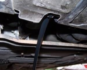
To improve (reduce) the pour point of these oils, pour point depressants (PPDs) are added. PPDs do not in any way affect the temperature at which wax crystallizes or the amount of wax that precipitates. They simply ‘coat’ the wax crystals preventing them to interlock and forming three-dimensional structures that inhibit oil flow. Good PPDs can lower the pour point by as much as 40 0 C, depending on the molecular weight of the oil.

While the pour point of most oils is related to the crystallization of wax, certain oils, which are essentially wax free, such as polyalphaolefins (POAs), have viscosity-limited pour points. With these oils the viscosity becomes progressively higher as the temperature is lowered until no flow can be observed. The pour points of these oils cannot be lowered with PPDs. However, due to PAOs’ unique nature, they provide excellent low-temperature viscometrics and very low pour points that cannot be achieved by adding PPDs to mineral oil.

Just as important as pour point (if not more) is Cloud Point. The cloud point of an oil is the temperature at which a cloud of wax crystals start to appear when a sample is cooled under prescribed conditions. Below this temperature, the viscosity of the oil increases exponentially with decreasing temperature. This may well lead to oil pump cavitation in oil circulating systems, even before the pour point of the oil is reached — particularly in systems where the oil pump is positioned higher than the oil reservoir. ASTM D2500 is the most commonly used test method to determine the cloud point of petroleum products.

Considering all the above a good rule of thumb is that the pour point of a lubricating oil should be at least 1 O O C below the lowest anticipated ambient temperature. This will ensure dependable lubrication and better equipment reliability in the long term.


Oiling gears

Lubrication regimes explained OilChat#22

Oiling gears

In response to OilChat #21 we have received requests to explain the different lubrication regimes (boundary, mixed and hydrodynamic) in more detail.

The regimes of lubrication can be compared to water skiing. Skiers normally start by entering the water with their skis on and holding onto the ski rope. When the skier is ready, the boat starts and the skis begin to move on the sand (boundary lubrication). As the boat accelerates, contact between the skis and sand is reduced (mixed lubrication). When the speed is sufficient, the skier rises out of the water with the front of the skis also out of the water and pointing upwards at an angle. It is this wedge profile between the skis and water that allows the skier to hydroplane on the water (hydrodynamic lubrication).


Before addressing lubrication reg1
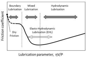
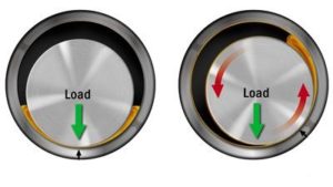
imes, we need to look at how friction and wear occur between moving machine surfaces. These surfaces appear smooth to the naked eye, but they are actually rough and uneven. Tiny peaks called asperities stick out and scrape against asperities on the opposing surface, causing friction and wear. The prime function of a lubricant is to prevent, or at least reduce, wear between surfaces moving on one another. We will endeavour to explain the lubrication of a plain journal bearing in parallel to the skiing analogy above. To enable the shaft to rotate in the bearing on the left, the diameter of the shaft must be less than the inside diameter of the bearing. This creates a wedge similar to the one between the skis and the water.


Boundary Lubrication is associated with metal-to-metal contact between moving surfaces. During start-up, t2
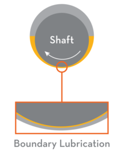
he shaft and bearing asperities in a lubricated system will be in physical contact. The major portion of wear in any machine takes place in this regime. To prevent excessive wear within this regime, lubricants are formulated with additives to form a low-friction, protective layer on the wear surfaces. The base oil of the lubricant acts as a carrier to deposit the additives where they are needed. A suitable viscosity is important to ensure the oil can flow into tight spaces to lubricate the surfaces. The additive chemistry (anti-wear or extreme pressure) used within the lubricant is determined by the application.

Mixed lubrication is a transitional regime between the boundary and hydrodynamic lubrication, sharing characteristics of both. Oil molecules are cohesive as well as adhesive and cling to the shaft. As the shaft gains rotational speed, oil is carried into the wedge and starts to lift the shaft, but not sufficiently to separate the two surfaces completely. Mixed lubrication can also occur between surfaces where high loads are encountered, such as when reciprocating pistons slide against cylinder walls. With mixed lubrication, wear protection depends on both the lubricant viscosity, as well as the additives within the oil formulation. A lubricant with a too low viscosity will result in excessive metal-to-metal contact between the shaft and bearing.

4

Hydrodynamic lubrication (also known as full film lubrication) occurs when speed and load are such that the oil wedge between the shaft and bearing separates the surfaces completely. This is the ideal condition to avoid friction and wear. In fact, as long as this condition exists, no anti-wear or extreme pressure additives are required, and friction is so low that bearings can operate indefinitely without wear. Any friction remaining comes from the cohesiveness of the oil molecules as they slide past each other during operation. A lubricant with too high viscosity will result in an increase in the oil’s molecular friction. This will in turn increase operational temperatures and energy loss.


The lubrication regimes discussed above pertain to surfaces sliding against each other, such as journal bearings, reciprocating pistons, gears, thrust bearings, chains and guide bearings. In addition to this there is yet another lubrication regime:

Elastohydrodynamic lubrication is the condition that occurs when a lubricant is introduced between surfaces that are in rolling contact, such as roller bearings. As the oil enters the contact zone between the roller and raceway (by rolling action), 5
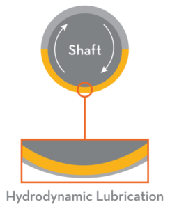
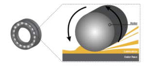
the pressure that develops is sufficient to separate the roller and raceway completely. In fact, the pressure is high enough for the surfaces to deform elastically. The deformation only occurs in the contact zone, and the metal elastically returns to its normal form as the rotation continues, hence the term elastohydrodynamic lubrication. This lubrication regime may be compared to a car tyre aquaplaning on water. It occurs when water on the road accumulates in front of the tyre faster than the weight of the car can push push it out of the way.

The curve below shows the transition of the lubricating conditions between sliding surfaces. The vertical axis represents the coefficient of friction (an indication of the amount of friction) between sliding surfaces. The horizontal axis is a function of the relative speed between the two surfaces:

6

The curve clearly illustrates that the coefficient of friction is the highest when speeds are low and boundary conditions prevail.  Anti-wear and extreme pressure additives play an important role in this regime. The coefficient of friction is reduced dramatically as speed is increased in the mixed lubrication regime. Once hydrodynamic lubrication is reached, the coefficient of friction is at its minimum. This is because there is no longer any physical contact between the two surfaces owing to the fluid film carrying the entire load. The remaining frictional force is due to the internal friction of the fluid (we mentioned earlier oil molecules are cohesive). When the sliding speed increases further, the coefficient of friction rises again owing to drag (increase in viscous resistance). If the equipment constantly operates in this condition, the viscosity of the oil being used should be reduced. it is therefore evident that oil viscosity is important in the hydrodynamic regime.


Please be aware that the above is a simplified explanation of lubrication regimes and it does not address factors such as Newtonian behaviour, pressure vector distribution, position of shaft in the bearing during the different regimes and bearing parameters.

Compressor

Compressor lubrication part 2 OilChat#21

Compressor

The majority of compressors require some form of lubrication to operate efficiently and reliably for extended periods of time. Oil-free compressors, such as those used to supply air for human consumption (where it is absolutely essential that the compressed air must not contain even minute traces of oil) are, however, the exception to the rule. This newsletter deals with the lubrication requirements of the most widespread compressor types that were discussed in OilChat #20.

Reciprocating Piston Compressors

The lubrication requirements of these positive displacement compressors are in many instances the most demanding of all compressor types. Regardless of size and configuration, all reciprocating compressors have similar components to be lubricated. These are pistons, piston rings, cylinder walls, valves, crankcase bearings and cross head components (if fitted). It is particularly important that reciprocating compressor oils should provide adequate protection against wear and deposit formation. The piston ring and cylinder contact area experience all the different lubrication regimes (i.e. boundary, mixed, and hydrodynamic) during every stroke of the piston. Boundary lubrication conditions occur near the top and bottom dead centre when the piston slows down to change direction of travel. This requires some form of anti-wear protection. Exposure of the lubricating oil to hot oxidizing conditions can be severe in reciprocating compressors. Some oil oxidation is inevitable, particularly in the discharge valve area. Adherence of oxidized residues to hot valve surfaces can be minimized by including a stable detergent/dispersant in the lubricating oil. An ideal lubricating oil for reciprocating air compressors would be made from a well-refined stable base oil with ashless anti-wear additives and good high temperature detergents/dispersants, along with oxidation inhibitors, foam suppressants and rust inhibitors for protection during shutdown. Viscosity requirements of reciprocating compressors are in the ISO viscosity range 68 to 220, or even higher for very high pressure, high temperature machines.

Rotary Screw Compressors

These positive displacement compressors use two intermeshing screw-shaped rotors for compression. The two major sub-categories are wet and dry screws. Dry screw designs have timing gears to synchronize the screw movement. However, the most common type of screw compressor is the flooded or wet screw design where the primary (male) rotor drives the secondary (female) rotor. In oil-flooded screw compressors the lubricant is injected into the air being compressed. The oil provides a lubricating and sealing film between the two screws. With these compressors the air and oil must be separated after compression. The major functions of the lubricant are to cool, seal, prevent rust and lubricate the bearings, rotors and shaft seals. In oil-flooded screw compressors there is intimate contact between the air and the lubricant, causing great potential for oxidation and deposits. The lubrication requirements of these compressors are similar to that of reciprocating compressors, except that the anti-wear requirements of screw compressors are not quite as demanding as reciprocating compressors. Viscosity requirements of screw compressors are in the ISO viscosity 32, 46, 68 or 100 range. Oil-flooded screw compressors are the main compressor type used for air compression in industrial applications.

Rotary Vane Compressors

Rotary (sliding) vane compressors consist of a rotor with a number of blades (vanes) in slots in the rotor. The rotor is mounted offset in its housing. Centrifugal forces ensure that the vanes are always in close contact with the housing. These compressors are available in oil-lubricated or oil-less designs. The type depends on the application, duty-cycle, and maintenance preferences. With non-lubricated variants, you replace the vanes with every service. When servicing oil-lubricated rotary vane compressors you replace the oil, filter and maybe the oil separator. Lubrication requirements of oil-lubricated rotary vane compressors are similar to those of oil-flooded (wet) rotary screw compressors. Oil is injected into the air (flooded lubrication) to cool, seal and lubricate the vanes, bearings and endplates. Obviously an oxidation inhibited oil is required. Contact of oil with the air suggests that a foam inhibitor would be beneficial. A rust inhibitor will provide protection against rusting during shutdown and for intermittent operation. In addition, the oil should have good detergent/dispersant properties to maintain a deposit-free circulating system and prevent vane sticking. The vanes may make contact with the cylinder walls in a boundary lubrication condition; therefore anti-wear oils are often used, ranging in viscosity from ISO 46 tol 50, depending on the application.

in more detail in the next issue of OilChat.

Dynamic Compressors

Radial Centrifugal and Axial Flow compressors use very high speed spinning blades or impellers to compress the air. These compressors do not require internal lubrication, hence only rust and oxidation inhibited oils are commonly used to lubricate and cool the outboard bearings. Due to the high speed, relatively low viscosity oils are used. The lubricant generally recommended for dynamic compressors is highly refined rust and oxidation inhibited oil of ISO 32 viscosity grade. Where a gear driven speed increaser is used, an ISO 46 or even ISO 68 viscosity grade may be required.

The same types of compressors that are used for air are also used for gases. Hydrocarbon based lubricants, mineral and synthetic (PAO), should NEVER be used for compressing active gases such as hydrogen, chloride, oxygen, etc. These gases may react chemically with hydrocarbon oils. Under pressure the chemical mixtures of these gases and hydrocarbon oil can be explosive. Lubricants blended with Group V base oils, normally polyalkylene glycol, should be used for gas compressors.

The choice of a compressor lubricant depends on the type and construction of the compressor, the gas being compressed, the degree of compression and the final outlet temperature. Most compressor manufacturers recommend lubricants that have been tested in their machines under controlled conditions. Make sure you are familiar with your manufacturers’ recommended lubricants, keep them in stock and adhere to the specified service intervals. If you don’t, your compressor may end up looking like this….

If you are in doubt our experts are at your disposal and ready to provide you with advice and answer any questions you may have. For more information, call 011 462 1829.