Diesel-Engine Oil

Two-stroke engine lubrication Part 1 OilChat#44

Diesel-Engine Oil

Two-stroke or two-cycle (2T) petrol engines have very specific lubrication requirements. The reason for this is that 2T engines have much higher oil consumption than four-stroke engines due to combustion of the lubricant with the fuel/air mixture. 2T engines also have a higher power to weight ratio than their four-stroke counterparts. To understand the specific lubrication requirements of two-stroke engines one must first look at the way a 2T engine operates.


A two-stroke engine completes a power cycle with two strokes (one up and one down movement) of the piston during one crankshaft revolution. This is in contrast to a four-stroke engine, which requires four strokes of the piston (Intake, Compression, Power and Exhaust) to complete a power cycle during two crankshaft revolutions. In a two-stroke engine the end of the combustion stroke and the beginning of the compression stroke happen simultaneously, with the intake and exhaust functions occurring at the same time.  Basic two-stroke engines do this by using the crankcase and the underside of the moving piston as a fresh fuel charge pump.

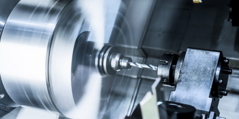
When the piston of a two-stroke engine rises on compression as shown in the illustration on the right, the underside of the piston creates a vacuum in the crankcase. The bottom of the piston skirt ‘opens’ an inlet port in the cylinder, allowing a mixture of petrol and air to flow into the crankcase from a carburetor. When the piston nears Top Dead Center, a spark ignites the compressed fuel/air mixture. The mixture burns and its chemical energy becomes heat energy, raising the pressure of the combusted mixture radically. This pressure drives the piston down the cylinder and rotates the crankshaft. While the piston continues down the cylinder, it begins to expose an exhaust port in the cylinder wall. As spent combustion gas rushes out through this port, the descending piston is simultaneously compressing the fuel/air mixture trapped beneath it in the crankcase.

While the piston descends further down, it begins to expose a transfer port which is connected to the crankcase by a short duct. Since the pressure in the cylinder is now low and the pressure in the crankcase higher, a fresh charge of fuel and air from the crankcase flows into the cylinder through the transfer port. The port and piston are shaped to minimize direct loss of fresh charge through the exhaust port. Even in the best designs there is some loss, but the simplicity of the 2T engine has its price! This process of filling the cylinder while also pushing leftover exhaust gas out through the exhaust port is called “scavenging”. While the piston is near Bottom Dead Center, fuel and air continue to flow from the crankcase, up through the transfer port, and into the cylinder. As the piston moves up again, it first covers the transfer port and then the exhaust port and the cycle is repeated.

If you are still not sure how a basic two-stroke engine functions, please follow the link below. It
shows an animated illustration of a simple two stroke engine and how the 2T cycle works. https://www.youtube.com/watch?v=xNLE8G3pC0k

Most late model two stroke engines have more sophisticated methods of introducing the fuel charge into the cylinder. These designs improve power and economy and include Reed Valves, Poppet Valves, Rotary Valves and Direct fuel injection.  An additional advantage of Direct Injection is that it eliminates some of the waste and pollution caused by carbureted two-stroke engines (where a proportion of the fuel/air mixture entering the cylinder goes directly and unburned out through the exhaust port). Direct fuel injection 2T’s are more efficient because the fuel is injected after the exhaust port closes and therefore more complete combustion occurs and more power is developed.

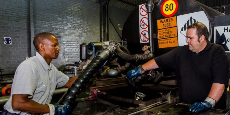
Since the fuel/air mixture is constantly being pumped by the crankcase and piston, it is not practical to lubricate the two-stroke engine with circulating oil from a sump (like a four-stroke engine) because the oil would be swept away by the mixture rushing in and out of the crankcase. In a 2T engine a little oil must therefore be mixed with the fuel (typically 2% to 5%) to lubricate the few moving components of the engine. Alternatively oil can be injected very sparingly, from a separate oil tank, into the engine with a tiny metering pump. The fact that there is so little oil dictates that two-stroke engines must employ rolling element bearings, which need only a whiff of oil for lubrication.

In the nexts issue of OilChat we will endeavour to clear some of the fallacies surrounding two-stroke oil.  If you have any questions concerning 2T oil in the interim, simply mail us at info@bcl.co.za. Our experts are at your disposal and ready to provide you with advice and guidance.


Q8Oils Lubricants

Lubricant shelf life OilChat#43

Q8Oils Lubricants

It is often asked what the acceptable storage life for lubricants and associated products is. Regrettably there is no simple straightforward answer to this question and to complicate matters, the storage life of the different types of lubricants is not the same.


In a recent survey Machinery Lubrication Magazine polled several lubricant suppliers to get their recommendations for lubricant storage life. The publishers were attempting to identify a consensus of opinion, or at least a reasonable range, to share with their readers as a best practice. They found a startling variation in responses and a concerning degree of disagreement. In some cases, those polled were apprehensive to respond, most probably because they have no control over storage conditions once the product leaves their plant. The storage environment greatly affects the estimated shelf life of lubricating oils and greases. The following conditions have a major influence on lubricant storage life:

Temperature – Both high heat and extreme cold can affect lubricant stability. Heat will increase the rate of oil oxidation. Cold can result in wax and possible sediment formation. In addition, alternating exposure to heat and cold may result in ‘breathing’ of drums and possible moisture contamination. A temperature range of -10°C to 45°C is acceptable for storage of most lubricating oils and greases. Ideally, the storage temperature range should be from 0°C to 35°C.

Light – Exposure to bright light may impact color and appearance. Lubricants should be kept in the original metal or opaque plastic containers they were supplied in.

Water – Water will react with some lubricant additives. It can also promote microbial growth at the oil/water interface. Lubricants should be stored in a dry location, preferably inside or at least under cover. When storage of drums outside is unavoidable, they should be placed horizontally (on their side) with the bungs in the 3 and 9 o’clock positions. This allows the water to drain off and not to be drawn into the drum.

Particulate Contamination – Lubricant drums and pails should not be stored in areas where there is a high level of airborne particles. This is especially important when a partially used container is stored for later use.

Atmospheric Contamination – Oxygen and carbon dioxide can react with lubricants and affect their viscosity and consistency. Keeping lubricant containers sealed until the product is needed is the best protection.

The estimated shelf lives on the following page apply to products stored in their original sealed containers, in a sheltered environment, at suitable temperatures and under good housekeeping conditions.  In addition, products should be used on a FIFO (First-In, First-Out) basis. FIFO rotation of stored products will ensure storage life is not accidentally exceeded.

ESTIMATED SHELF LIFE OF FINISHED PRODUCTS

AUTOMOTIVE PRODUCTS STORAGE LIFE
All Automotive Lubricants (PCMO, HDMO, 2T Oils, ATF, AGO, STOU, UTTO, etc.) 3 Years
Brake Fluids (in their original sealed containers) 1 Year
Antifreeze Coolants 3 Years
   
INDUSTRIAL LUBRICANTS  
All mineral based lubricants 3 Years
PolyAlphaOlefin based lubricants 3 Years
Ester based lubricants 3 Years
PolyGlycol based lubricants 2 Years
Soluble metal working fluids 9 Months
Neat metal working fluids 18 Months
Neat forming oils, protective oils and spark erosion fluids 3 Years
   
GREASE  
NLGI GRADE ≥ 1     Lithium and lithium complex, lithium/calcium complex, aluminium complex, barium and calcium sulfonate grease

Aluminium, bentonite clay, calcium & calcium complex, sodium, polyurea and silicon greases 

3 Years


2 Years

NLGI GRADE <1     All thickeners 2 Years


NOTE: The estimated shelf lives in the table above apply to products stored in their original sealed containers, in a sheltered environment, at suitable temperatures and under good housekeeping conditions.

HTHS viscosity

High temperature, high sheer viscosity OilChat#42

HTHS viscosity

OilChat #41 dealt with Fuel Economy and Wear in engines as well as the impact of the SAPS (sulphated ash, phosphorus & sulphur) content of engine oils. This newsletter takes it a step further and addresses the significance of high temperature high shear (HTHS) viscosity of engine oil. HTHS viscosity is a critical oil property that relates to the fuel economy and durability of engines. The HTHS test is a simulation of the shearing effects that occur in engines. It is a measure of the resistance of oil to flow under conditions resembling highly loaded journal (crankshaft) bearings in engines running at elevated temperatures and high loads.  Standard HTHS viscosity measurements are performed at 150°C and a specified shear rate.

New global and local government vehicle regulations demand better fuel economy and a reduction in greenhouse gas emissions. One of the ways that this can be achieved is by using lower HTHS viscosity engine oils.  Multigrade lubricants developed for use in automotive engines often contain polymeric viscosity modifiers. The contribution of such viscosity modifiers (VMs) to the viscosity/thickness of oil decreases when the VMs are exposed to the high shear conditions found in critical engine components such as ring/liner interfaces, journal bearings and valve drive components.

Under normal operating temperatures (70°C to 100°C), the HTHS viscosity of engine oil is inversely proportional to fuel economy. HTHS viscosity is measured in centiPoise (cP). It should be noted that 1 cP is equal to 1 milliPascal second (mPa.s) since some specifications list mPa.s rather than cP. Bench tests have indicated that a lower HTHS potentially improves fuel economy at a rate of 0.5% to 2.0% for each 0.5 cP reduction in HTHS viscosity, depending on the engine type and operating conditions.

A too low HTHS viscosity however may affect engine durability. Decreased oil film thickness can lead to boundary lubrication conditions and increased wear. It can also cause lower oil pressure when the engine is idling at operating temperature. Even worse, under high stress conditions permanent viscosity loss may occur due to shearing of polymeric viscosity modifiers. It is therefore no surprise that the Society of Automotive Engineers’ SAE J300 Engine Oil Viscosity Classification System includes HTHS limits to ensure that engine oils can be relied on to provide the necessary lubrication under high temperature high shear conditions. The thinner the viscosity grade, the lower the required HTHS viscosity. For instance, SAE J300 specifies an oil must have a HTHS viscosity of 3.7 cP or higher in order to be classified as a SAE15W40 viscosity grade, whilst the minimum limit for a SAE 5W30 is only 2.9 cP.

HTHS viscosity limits are also incorporated in the latest American Petroleum Institute (API) diesel engine oil specifications:

API CK-4 defines oils for use in four-stroke diesel engines designed to meet 2017 model year on-highway and Tier 4 non-road exhaust emission standards These oils are also suitable for older diesel engines. API CK-4 oils are designed to provide enhanced protection against viscosity loss due to shear and have a minimum HTHS viscosity of 3.5 cP.  API CK-4 oils exceed the performance criteria of API CJ-4, CI-4 Plus, CI-4, and CH-4 and can effectively lubricate older engines demanding these API Categories.

API FA-4 describes certain SAE XW-30 oils specifically formulated for use in selected four-stroke diesel engines designed to meet 2017 model year on-highway greenhouse gas (GHG) emission standards.

These oils are formulated to provide enhanced protection against viscosity loss due to shear and are
blended to a HTHS viscosity range of 2.9cP to 3.2cP to assist in reducing GHG emissions. API FA-4 oils
are neither interchangeable nor backward compatible with API CK-4, CJ-4, CI-4 Plus, CI-4, and CH-4 lubricants. Operators should refer to the engine manufacturers’ recommendations to determine if API FA-4 oils are suitable for use in their specific engines.

The HTHS viscosity requirements of the European Automobile Manufacturers’ Association (ACEA) are a bit more complicated. The three classes of ACEA engine oils are listed in bold below. These three classes are further divided into subcategories to meet the requirements of different engines in each class:

Class A/B: Petrol and Diesel Engine Oils (Higher SAPS)

A5/B5 oils have lower HTHS viscosities (2.9 to 3.5 mPa.s), indicating they provide better fuel economy but they may not provide adequate protection in engines that are not designed for such oils. ACEA A3/B3 and A3/B4 on the other hand require oils with higher HTHS viscosities (≥ 3.5 mPa.s), suggesting they may not be as fuel efficient as an A5/B5 oil, but they could offer better engine protection in certain engine designs.

Class C: Oils for Petrol & Diesel Engines with Emission Control Devices (Lower SAPS)

The categories within the C class are divided along SAPS limits and along HTHS viscosities. C1 and C4 are low SAPS oils, while C2 and C3 are mid-SAPS oils. At the same time C1 and C2 oils have lower HTHS viscosities limits (2.9 mPa.s max), while C3 and C4 oils have higher HTHS viscosities (3.5 mPa.s max). The C5 category has the lowest limit for HTHS viscosity. In order for an oil to meet this specification it must be a mid-SAPS oil and its HTHS viscosity has to be between 2.6 and 2.9 mPa.s.Class E: Heavy Duty Diesel Engine Oil

All categories in this class must have a minimum HTHS viscosity of 3.5 mPa.s to ensure adequate engine protection.  In the E class the SAPS content and the drain interval make the difference. E4 and E6 oils offer significantly extended drain intervals (where the engine manufacturer allows it) while E7 and E9 are designed for extended drain applications. E6 and E9 oils have limited SAPS content, which means they can be used in engines that require these oils, such as Euro VI engines.

To complicate matters many engine manufacturers now also include HTHS viscosity limits in their engine oil specifications. All this may appear rather complex and it is indeed. What you should remember thou is the following:

  • Lower SAE viscosity grade oils typically have lower HTHS viscosities,
  • Lower HTHS viscosity tends to improve fuel efficiency, which lowers GHG emissions,
  • Higher HTHS viscosity affords better wear protection, ring and liner scuffing in particular,
  • A careful balance must be found when selecting engine oil.

If you have any questions concerning HTHS viscosity, or need assistance to select a suitable oil for your engines, simply mail us at info@bcl.co.za. Our experts are at your disposal and ready to provide you with advice and guidance.

Used Oils and Lubricants

Used oil industry offering significant job creation

Used Oils and Lubricants

The used oil industry in SA is bucking the current trend and creating a significant number of jobs. 

According to the latest figures from the Quarterly Employment Statistics (QES) survey, released by Statistics South Africa, South Africa has seen a decrease in the number of jobs being created.  However, a survey commissioned by The ROSE Foundation (Recycling Oil Saves the Environment) shows that a significant number of jobs have been created through the recycling of used oil.


According to the research house conducting the study, The Research LampPost, the results indicate that approximately 1,300 staff ranging from drivers, labourers and administrators, to operators and managers, are employed in the sector.


Data from 84 licensed collectors and 11 licensed processors and 13 licensed bulking points, was included in the study. This was then used as a basis to estimate the total employment contribution for the collection and processing of an estimated 120 million litres per annum of used oil in South Africa.


Demographically, the employment profile is predominantly male (85%) and African (64%). In larger operations, the top management is mostly African (37%) or white (34%). In smaller businesses, the sole operators are 41% African, 41% white, 12% Indian and 6% coloured.


The majority of collectors and processors are situated in Gauteng, where the biggest volumes are collected. Nearly 50% of the oil is collected in Gauteng. The bigger collectors (600kl/pa or more) collect 75% of the used oil identified in the study.


The study results show the used oil industry as a highly competitive business, with most collectors saying that the biggest challenges they faced were fierce competition and pricing, which in turn affected their profit margins and sustainability. Despite this they continue to operate and many of the part-time collectors show entrepreneurial flair in combining used oil collection with other services such as selling automatic lube systems, fire suppression, garage equipment and hydraulics, hazardous waste removal, scrap metal collection, cleaning wash bays and collection and processing of plastic oil bottles and used oil filters.


“This is a recycling success story – the used oil industry is a sustainable sector that not only employs many people but also effectively supports their dependents,” commented ROSE Foundation CEO, Bubele Nyiba. On average each collector participating in the study supports 4.2 dependents.


“Recycling can only work if it is economically sustainable and the ROSE foundation’s challenge is to ensure the environmental imperative is supported by an effective recycling business model – we offer support in the form of training, audits, equipment and incentives, and we work with all the lubricants industry stakeholders towards continuously increasing recycling volumes.”

For more information and to find out about registered collectors and processors contact the ROSE Foundation on (021) 448 7492 or visit www.rosefoundation.org.za.


Fuel Economy oil

Engine oil fuel economy vs wear OilChat#41

Fuel Economy oil

In this final OilChat of 2018 we debate a rather controversial topic: Fuel Economy vs Wear in engines. It is often believed engine oils that increase fuel economy reduce friction and therefore prolong engine life. This theory is challenged in our newsletter.

To start off we should face the fact that many drivers do not really care about fuel economy. This is confirmed by the number of SUVs, 4X4s, Double Cabs and Bakkies we see on the road. The size and weight of these vehicles are not conducive to great fuel economy. Furthermore, consider how most vehicles are driven. Anyone driving slower than the speed limit to conserve fuel is a danger to himself and other drivers that are not all that concerned about saving fuel and drive at higher speeds.

Vehicle manufacturers, on the other hand, are very concerned about fuel economy. Thinner, low viscosity oils are nowadays being used for three reasons: They save fuel in test engines, viscosity rules have changed, and vehicle manufacturers are recommending thinner grades. Traditionally SAE 20W-50 and SAE 15W-40 multigrade engine oils were used, but today many manufacturers recommend oils as thin as SAE 5W-30 and even SAE 5W-20. This seems ridiculous. SUVs and LDVs, with their brick-like aerodynamics and inherently less efficient four-wheel drive configurations, need powerful, fuel-guzzling engines to move their weight around and vehicle manufacturers recommend thin oils to save some fuel.

Thinner oils have less drag, and therefore less friction and wear. Correct? Perhaps this is true in test engines or engines in light-duty operation. Thicker oils, however, may offer better protection for more severe operations such as driving over mountains, towing a trailer or caravan, overloading, high-speed driving, overheating or dusty conditions. Any abrasive particles (such as dust/sand) equal to or larger than the oil film thickness will cause wear. Filters are necessary to keep out larger oil contaminants. The other side of the equation is oil film thickness. Thicker oil films can accommodate larger contaminants.

To make things worse, modern engine oils must have lower SAPS (sulphated ash, phosphorus, and sulphur) levels since high SAPS oils can damage catalytic converters. Phosphorus is part of the zinc phosphate (ZDDP) anti-wear additive. To reduce SAPS you need to reduce the amount of antiwear additive in the oil. Antiwear additives are important in the absence of a hydrodynamic oil film, such as in the valve drive train (please refer to OilChat #22). On the other hand, if engine wear causes oil consumption to increase, the risk of forming phosphorus deposits in the converter increases dramatically. It, therefore, seems that preventing wear and oil consumption should be a priority. In the past, oil formulators could make a premium product by simply adding more ZDDP. A similar move today would result in an oil formulation that would not support new vehicle warranties.

As wear increases, the efficiency of an engine declines. Valve drive train wear changes valve timing and movement. Ring and liner wear affect compression. The wear reduces fuel efficiency and power output. Efficiency continues to decline as wear progresses. Perhaps optimizing wear protection is the way to reduce fuel consumption over the entire life of the engine? Certainly, engines that have experienced significant ring and liner wear benefit from thicker oils. The use of thicker oil results in compression increase, performance improvement, and reduced oil consumption.

High-mileage lubricants are a relatively new category of engine oils. These products typically contain more detergent/dispersant and antiwear additives than ‘modern’ engine oils. They also contain a seal swell agent (to reduce oil leaks) and are available in thicker viscosity grades than most vehicle manufacturers recommend for new vehicles. Perhaps high mileage may be better described by as soon as your vehicle is out of warranty?

Although thinner oils with less antiwear additive outperform more robust products in fuel economy tests, it is not clear that such products save fuel over the life of the engine. Every engine oil is a compromise. Oils recommended by vehicle manufacturers seem to compromise wear protection under severe conditions to gain fuel economy and catalyst durability. It is important to recognize that the use of engine oil that offers more wear protection will most likely compromise your warranty. Thicker oils also compromise cold temperature flow, which may be of concern, depending upon climate and season.
For out of warranty engines in Southern Africa, the best protection against wear is probably a product that is a little thicker (SAE 10W-40 or even SAE 15W-40) and with more antiwear additives than the oils that support the manufacturer’s warranty.

The best oil for your vehicle depends on your driving habits, the age of the engine, operating conditions and the climate you drive in, but it is not necessarily the type of oil specified in the owner’s manual. If in doubt our experts are at your disposal and ready to provide you with advice and guidance. Simply mail us at info@bcl.co.za.
We would also like to make use of this opportunity to wish all our readers a wonderful Festive Season and a prosperous New Year. We are certainly looking forward to chatting with you again in2019.

Limited Slip Lubricants SA

Limited slip differential lubrication OilChat#40

Limited Slip Lubricants SA

Without a limited slip differential (diff) cars, trucks and off-road vehicles cannot turn without their inner driving wheels spinning or the outside ones dragging and skidding over the road or ground. Automotive differentials allow the outer drive wheels to rotate faster than the inner drive wheels during a turn. This is necessary since when cornering, the inner wheels travel a shorter distance than the outer wheels.

Conventional differentials direct power to the wheel with the least resistance by nature of their design. The disadvantage of this is that one driving wheel can spin wildly while the opposite wheel receives insufficient power to move the vehicle. With a conventional diff, the right front wheel of the Jeep in the photo will turn uncontrollably whilst the left front wheel will not have adequate power to move the vehicle. To overcome this problem many vehicles are fitted with limited-slip differentials (LSDs). Limited Slip Lube

To understand the operation of LSDs one needs to know how a conventional differential works. A diff has one input and two output shafts (the axles that connect to the driving wheels) as shown in Figure 1. The input shaft is coupled to the pinion gear, which in turn drives the big ring (crown) gear.  A ‘cage’ that carries two smaller pinion gears is fixed to the ring gear. These pinion gears in turn mesh with two side gears that are connected to the end of each axle shaft. The pinions and side gears in the cage allow the driving wheels to rotate at different speeds when cornering as illustrated in the video link https://www.youtube.com/watch?v=S9NKB0VoR2I.

Limited Slip Differential Lube 1Limited Slip Differential Lube


A limited slip differential can be described as a locking mechanism that allows one wheel to slip or spin while some torque is still delivered to the other wheel. The clutch-type LSD is the most common version of the limited slip differential. This type of LSD has all the same components as a conventional diff plus a spring pack and a set of clutches as shown in Figure 2.

The spring pack pushes the side gears against the clutches, which are attached to the cage. The side gears spin with the cage when both wheels are moving at the same speed, and the clutches are not really needed. The only time the clutches step in is when something happens to make one wheel rotate faster than the other, as in a turn. The clutches fight this behavior, wanting both wheels to rotate at the same speed. If one wheel wants to spin faster than the other, it must first overpower the clutch. The stiffness of the springs and the friction of the clutch determine how much torque it takes to overpower it.

Getting back to the situation where one drive wheel is off the ground and the other one has good traction, the limited slip differential will direct enough power to the wheel with traction to move the vehicle even though the one wheel is in the air. The torque supplied to the wheel on the ground is equal to the amount of torque it takes to overpower the clutches. The result is that you can move forward, although not at full power. The same principle will apply when one wheel loses traction because of mud, sand, ice, water, etc.

The most critical area in a differential in terms of lubrication, hypoid diffs, in particular, is the contact area between the crown and pinion (see OilChat #14 for more details). API GL-5 extreme pressure (EP) lubricants are typically recommended to lubricate the crown and pinion effectively.  Such ‘slippery’ gear lubricants may, however, cause chatter in LSDs. This happens when the clutches repeatedly alternate between slipping and sticking (stick-slip), instead of slipping smoothly. Chatter not only generates annoying noise and vibration, it also causes premature wear. To overcome chatter, gear oils for LSDs are formulated with special friction modifiers to ensure smooth operation of the spring-loaded clutch packs.

Blue Chip Lubricants and Q8Oils have a complete range of limited slip gear oils to prevent chatter in LSDs. If you have any questions concerning limited slip gear oils, our experts are at your disposal and ready to provide you with advice and guidance. Simply mail us at info@bcl.co.za.

Final words of advice: If stuck in mud or sand with a rear wheel drive vehicle without a diff lock or LSD, pulling up the handbrake moderately and applying power to the rear wheels may well get you out of trouble. By doing this you basically even out the traction/slip on the back diff and it acts as a diff lock to some extent.

Slideway Oil Gauteng

Slideway lubricants OilChat#39

Slideway Oil Gauteng

In this edition of the newsletter, we will endeavour to explain what slideway lubricants are, their functions and how they work.

Slideway oils derive their name from the application. They are primarily designed for the lubrication of machine tool slideways. A slideway can be described as any form of track along which things can slip or slide. A curtain rail is a simple example of a slideway.

In metalworking operations, workpieces are machined into a desired shape and size by a controlled metal removal process. In Slideway Oil Johannesburg
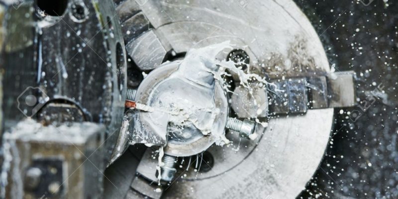
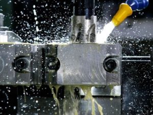
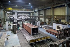
general cutting operations (e.g. lathes) the workpiece rotates whilst the cutting tool is stationary. Metal may also be removed by means of linear instead of rotational movement.  In these operations, the workpiece and cutting tool move in a straight line relative to each other. The photo on the right shows such a machining operation.  The cutting head (in the red rectangle) is attached to the light grey frame and can move up, down or to the left and right on slideways. The brown workpiece is fixed to a traverse table that moves backward and forward, also on slideways.  The operator (with green pants) is visible on the left side of the photo. These metalworking machines can vary in size from modest basic units that produce small metal components to massive monsters designed to machine very large workpieces such as marine engines and mining machinery.

Smooth and precise slideway operation is essential to ensure optimum machine tool productivity since loss of frictional control can cause inaccuracies of the machined workpiece surfaces. To fully understand slideway lubrication we need to revisit the fundamentals of friction and lubrication – please refer to OilChat 22. The speed/friction relation between two lubricated surfaces is illustrated by the curve on the second page of OilChat 22. The three different lubrication regimes are:

  • Boundary Lubrication is associated with metal-to-metal contact when the speed difference between two moving surfaces is too low to prevent contact between the two lubricated surfaces.
  • Mixed Lubrication is a transitional regime between the boundary and hydrodynamic lubrication when the speed is not sufficient to separate the two surfaces completely.
  • Hydrodynamic Lubrication occurs when the speed is high enough to separate the two moving surfaces completely and friction is at its lowest.

In machining operations, the traverse table stops at the end of the slideway and starts to move in the opposite direction. When the table stops, static friction (the worst form of boundary lubrication) occurs.  As the table speed increases, friction changes from static to dynamic. This fluctuation between static and dynamic friction results in a jerky movement which is commonly referred to as stick-slip. In simple terms stick-slip can be described as surfaces alternating between sticking to each other and sliding over one another. Static (stationary) friction between two surfaces is greater than dynamic (moving) friction. If the applied force is large enough to overcome the static friction, the reduction in friction to the dynamic state can cause a sudden increase in the velocity of the movement resulting in the jolting action. Stick-slip can also occur at low feed speeds and high loads. Since stick-slip is a recurring event, it may be perceived as a harmonic vibration or noise.

While it may not always be visible to the human eye, stick-slip effects are a frequent phenomenon in everyday life and it produces a range of audible incidents, e.g. when a chair is pushed along the floor its legs begin to vibrate with an irritating noise. Other examples of stick-slip motion are the sound produced by a wine glass when a wet finger is moved along its rim and the jerky motion of vehicle windshield wipers. Stick-slip, however, is not always a bad phenomenon. It is responsible for the rich sounds when a bow is moved over the strings of a violin. In machining operations, stick-slip is an undesirable occurrence that causes the transverse table and workpiece to shudder resulting in inaccuracies of the machined surfaces.

Slideway lubricants are therefore formulated with special friction modifying additives to control stick-slip and chatter under all operating conditions including:

  • Static friction situations during start-up.
  • Continuous transition from rest to movement.
  • Slow speed heavy load applications.

In addition, high-performance slideway lubricants must contain additives to provide good antiwear and extreme pressure performance, tackiness for slideway adhesion, oxidation stability, as well as rust and corrosion protection for slides and ways. Slideway oils must also have good compatibility with cutting oils and other machine tool lubricants and adequate demulsibility to separate from cutting fluid emulsions.

The most common slideway lubricant viscosity grades are ISO 68 and ISO 220 with the following application guidelines:

ISO 68: Horizontal slideways and light to moderate applications.

ISO 220: Vertical slideways and more severe applications.

Slideway oils in the appropriate viscosity grade are also recommended for hydraulic systems subject to stick-slip service (ISO 11158 Type HG), heavily loaded gear systems and other industrial applications requiring an adhesive, corrosion inhibited lubricant with EP properties.

If you have any questions concerning slideway lubrication our experts are at your disposal and ready to provide you with advice and guidance. Simply mail us at info@bcl.co.za.

metal working fluids

Metalworking fluids OilChat#38

Metalworking Fluid

Manufacturers with metalworking operations and machine shops use and dispose of a substantial amount of metalworking fluid each year. These operations have the potential to extend metalworking fluid life. Prolonging the life of the metalworking fluid and optimizing its performance are very dependent on the control of the metalworking fluid system. This control is as important as the selection of the proper fluid (please refer to OilChat #37).

Regardless of the fluid type and application, all metalworking fluids require some form of management. Neat oils are relatively easy to maintain, but they do require some management. Straight oils should be filtered on a regular basis to remove metal fines and other contaminants to provide a long service life, improved cutting performance and a high level of surface finish. The majority of cutting and grinding fluids in use today, however, are water soluble. These fluids, on the other hand, differ from straight oils because they require a higher degree of maintenance to provide extended periods of satisfactory cutting performance, bio-stability, and longevity.metal working fluid

When a soluble metalworking fluid is mixed with water, a new level of potential problems is presented. The coolant sump is an excellent breeding space for bacteria, fungi, yeasts, and moulds because it is dark, humid and provides an excellent nutrient source (the fluid itself) for bacteria to thrive on as shown on the right. If you are familiar with metalworking facilities you have probably encountered a variety of unpleasant odours. You must have noticed that “rotten egg” or “Monday morning” smell (bacteria) when metalworking fluids have been allowed to settle over the weekend.

The majority of cutting and grinding fluids in use today are water soluble. Over time, these fluids can become rancid or contaminated with microbiological growth. With use, fluids lose their rust control capabilities, as well as their anti-foam characteristics. During normal fluid use, evaporation of water increases the concentration of the metalworking fluid. In addition, the fluids contain the chips and “fines” from the machining operation. During use, the cutting fluid collects hydraulic oil and other lubricants from the machine tool. This oil, called tramp oil, contributes to the growth of bacteria. These micro-organisms smell like rotten eggs and shorten fluid life. The fluid is disposed of once its efficiency is lost. Good fluid management practices can go a long way towards solving fluid problems and making the most cost-effective use of metalworking fluids.

Monitoring and maintaining fluid quality are crucial elements of a successful fluid management program. Important aspects of fluid monitoring include system inspections and periodic measurements of fluid parameters, such as concentration, biological growth, and pH. Changes in optimal fluid quality must be corrected with appropriate adjustments (such as fluid concentration adjustments, biocide addition, tramp oil, and metal cuttings removal and pH adjustment). It is important to know what changes are taking place in your system and why they occur. This allows you to take the appropriate steps needed to bring fluid quality back in line and prevent fluid problems from recurring.

Many of the contaminants that cause fluids to be disposed of prematurely are foreign materials, such as floor sweepings, cleaners, solvents, dirt, tobacco, food, etc. If improved fluid life is a goal, it must start with education and revised shop practices. The first step in fluid control is improved housekeeping and sanitation. Only then control of natural metalworking fluid contaminants, such as chips, fines, tramp oil, and bacteria will be effective in improving fluid life.


The link below provides more information and advice on how to manage water miscible and neat metal-working fluids at every stage from ‘’cradle to grave”. It aims to give a broader understanding of cutting fluid management and provides practical advice to get the best results from metalworking fluids.

https://www.q8oils.com/Portals/0/Pdf/Q8%20POCKET%20MWF%20GUIDE%20ENGLISH%202015%20new%20brand%20v1.pdf

metalworking

Metalworking fluids OilChat#37

metalworking

Metalworking is a collective name for a variety of machining processes whereby metal is brought to a specified geometry by removing excess material by means of various kinds of cutting and grinding operations. The net result of metalworking is two products: the finished workpiece and waste. Depending on the machining operation, the waste can be metal swarf (small gritty chips or filings), shavings, turnings or stringy tendrils.

metal-working

Enormous amounts of friction and heat are generated at the cutting interface between the cutting tool and workpiece during the metal removing process. Metalworking fluid (MWF) is used to reduce friction and heat during the machining operation. MFW must also improve workpiece quality, reduce cutting tip wear, remove swarf, improve process productivity and protect the workpiece and machine tools against rust and corrosion. The MWF is generally applied by a spray across the face of the tool and workpiece as shown in the milling operation on the right.

Most MWFs presently in use fall into one of the following two categories:

Neat Metalworking Fluids – also referred to as cutting oils. These are non-emulsifiable fluids and are used in machining operations in undiluted form. They are composed of base oils and normally contain polar compounds such as esters and fatty acids (corrosion inhibitors and lubricity agents), as well as extreme pressure (EP) additives. Typical EP additives are Chlorine, Phosphorus and Sulphur. Neat oils provide the best lubrication and are most effective at reducing friction.

Soluble Metal Working Fluids – often called emulsifiable cutting fluids because they form an emulsion when mixed with water. The concentrate consists of base oil (mineral, synthetic or semisynthetic) and emulsifiers to produce stable emulsions when mixed with water. In addition typical soluble MWFs formulations include a selection of the following additives: EP agents, rust and corrosion inhibitors, coupling agents, biocides, antifoam agents, scents and dyes.

Synthetic based soluble MWFs provide the best performance as far as cooling, tool life and resistance to bacterial growth (increased sump life) is concerned. In some metalworking operations workpiece visibility is important. Synthetic MWFs form clear transparent solutions, whilst mineral and semisynthetic formulations form milky (see photo above) to semi-transparent emulsions.

Soluble MWFs are always used in diluted form, generally in 3% to 10% concentrations. Soluble grinding fluids may be used in concentrations as low as 1%. Emulsifiable MWFs provide the best cooling and heat transfer performance. Consequently water soluble coolants have become vital in achieving the higher feeds and speeds required to ensure maximum production efficiency. They are widely used in industry and are the least expensive among all cutting fluids.

There are various issues to consider when selecting a MFW. These are the metals to be machined, the machining operations, machine types, tooling requirements, downstream plant processes and finally chemical and environmental restrictions. Discussions in this newsletter will be restricted to the two most significant aspects:

Metals

Some metals are more difficult to machine than others. Stainless steel, complex alloys and very hard metals demand a very high level of performance from the cutting oil. Other metals, like brass and aluminium, are easy to machine with general purpose oils. Where tough, difficult to machine metals are involved, highly additized cutting oils with excellent EP properties and anti-weld capability are required. Quite often these oils contain active sulphur and chlorine to protect the cutting tool and to ensure good workpiece finish. For brass, aluminium, many carbon steels and low-alloy steels, cutting oils with lubricity additives, and mild EP/anti-weld performance are sufficient. These oils are generally formulated with inactive sulfurized fat and/or chlorinated paraffin. Cutting oils formulated with active sulphur should not be used for brass and aluminium, as they will stain or tarnish the finished parts. Oils formulated for brass and aluminium are often called “non-staining” oils.

Machining Operations

Following is a list of the most common machining operations in order of increasing severity:

  • Sawingmetal-working-oil
  • Turning
  • Milling
  • Drilling
  • Grinding
  • Reaming
  • Honing
  • Gear Hobbing and Shaping
  • Tapping and Threading
  • Broaching

Easy machining operations (turning, milling, drilling, etc.) can be performed at higher speeds and require high levels of cooling with only modest EP capability. Soluble MWFs are generally used for milder operations. When a neat cutting oil is preferred for easy machining operations for whatever reason, the operations can be performed with lower viscosity, lightly additized fluids.

Difficult machining operations must be run at lower speeds and require a great deal of anti-weld protection. Oils designed specifically for the most severe operations, like thread cutting or broaching, are generally higher in viscosity and loaded with EP additives, like active sulphur and chlorine.

Although this brief discussion of metalworking fluid selection criteria demonstrates the complexity to select the proper cutting fluid, there is light at the end of the tunnel. MWF product data sheets (PDS) will normally indicate for what metals and machining operations the particular product is suitable. For soluble oils the PDS will also give an indication of what mixing ratios should be used for the various machining operations. If you are still in doubt our experts are at your disposal and ready to provide you with advice and answer any questions you may have. For more information simply mail us at info@bcl.co.za


Engine-Oil

Detergent dispersant additives OilChat#36

Engine-Oil

Motor oil deteriorates during its life in the engine due to oxidation. This results in sludge, varnish and resins that become deposited on engine surfaces. Deposits in the piston ring belt area cause ring sticking, loss of compression and increased oil consumption. Deposits can also block oil lines and passages which prevent the oil from reaching parts that need to be lubricated. The results are increased wear, heat build-up and eventual engine failure.

Engine oil is also contaminated with fuel soot because of incomplete combustion of the fuel as well as carbon which is introduced into the engine by emission control systems – diesel engine oil in particular. Oil viscosity increases with soot loading. High oil viscosity leads to cold-start problems and risk of oil starvation. When the soot concentration reaches a level that can no longer be suspended in the oil, the soot precipitates out of the oil to form sludge and deposits. High concentrations of soot also lead to increased wear.

To control all these contaminants, engine oils are formulated with detergents and dispersants in the performance additive package. Antiwear agents, rust inhibitors, and antioxidants are also incorporated in the performance package. In addition, multigrade oils contain viscosity index improvers. The viscosity index improver additive cannot be included in the performance package and is mixed into the oil separately. Pour point depressants and foam inhibitors are also included in the oil formulation, normally blended into the oil as separate components.

The performance package is dominated by the detergent and dispersant components. Considering the large amounts of contaminants the oil must handle (soot particles in particular) these two additives normally make up between 60% and 80% of the performance package. The terms ‘detergent” and ‘dispersant’ are often used interchangeably because the two additives work in synergy to keep engines clean, but the way they function is completely different.

Detergents are oil soluble organo-metallic compounds, mostly derived from the organic soaps or salts of calcium, magnesium or sodium, with calcium being the most commonly used. They have polar heads which allow them to cling to metal surfaces. Detergents serve two principal functions. Firstly, they remove deposits from metal surfaces inside the engine. Deposits and metal surfaces are both polar and deposits are drawn to the metal surfaces and stick to them. The detergent, with its stronger charge, displaces deposits from the metal surface as shown in Fig 1. Secondly, detergents are highly alkaline and neutralize acids formed in the oil by chemically reacting with them to form harmless neutralized chemicals.

fig 1                                   fig 2
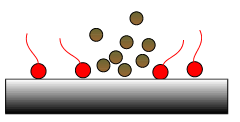
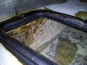
Fig 2: Dispersants hold deposits in suspension.

Fig 1: Detergents remove deposits
from metal surfaces.

Due to their metallic nature detergents are prone to produce residues and ash when burned in the engine.

Dispersants are polar additives that dissolve sludge and soot to prevent them from agglomerating, settling out and forming deposits. Dispersant molecules consist of an electrically charged polar head and a long, oil soluble tail. The polar heads attract and ‘embrace’ potential deposit forming materials and acids which are taken into

solution in the oil by the tails as illustrated in Fig 2. Dispersants do not contain any metallic elements. If they are burned in the engine, they do not leave any residue or ash.

Due to their alkaline nature, detergents and dispersants contribute to the alkalinity reserve or Total Base Number (TBN) of engine oil. Of these two additives, detergents add the most to TBN. Dispersants are more rapidly depleted than detergents because of the way they react with contaminants and acids in the oil.
Detergents, on the other hand, have the ability to retain their alkalinity reserve over longer periods of time, thus providing better TBN retention. We mentioned earlier that detergents produce ash when burned in the engine (due to their metallic nature) and therefore they contribute to the SAPS (Sulphated Ash, Phosphorus and Sulphur) level of engine oil.

Nowadays the main driving force for the development of new engine oils is concern over the environmental impact of engine emissions. Current generation lubricants must provide optimum exhaust gas emission control system durability. To protect these systems, engine oils must contain lower SAPS levels since SAPS can poison emission control after-treatment devices. The reduction in oil SAPS limits has resulted in a shift from traditional engine oil technologies to alternative low ash additive chemistries and there is now increased focus on detergents and dispersants derived from polybutenes.