Compressor

Compressor lubrication part 1 OilChat#20

Compressor

A compressor can be described as a pump or other device that ‘inhales’ air and delivers it at a higher pressure. Compressors are also used to compress a variety of gases. The very first air compressor was the human lung. To illustrate, we use compressed air from our lungs to inflate balloons. In the early days of mankind our ancestors used their breath to stoke fires and to increase the temperature of glowing coals. With the advent of the Metal Age more heat was required to melt metals, such as gold and copper, and circa 1 500 B.C. a basic type of air compressor, called bellows, was invented. This device was a hand-held, and later foot-operated, flexible bag made of animal skin, that produced a concentrated blast of air that was ideal for achieving higher temperature fires. In 1 762 during the early days of the Industrial Revolution John Smeaton, an innovative engineer, designed an air blowing cylinder driven by a water wheel. It soon replaced the bellows in many industrial applications.

Today compressors are generally driven by electric motors, turbines or internal combustion engines. Modern compressors come in many designs and sizes, ranging from small units at petrol stations to inflate car tyres, to massive industrial machines that are too large to fit into an average-sized garage. The air pressure in car tyres is usually between 2 and 3 bar (29.0 and 43.5 pounds per square inch). The latest high-performance compressors can deliver pressures well in excess of 70 bar (more than 1000 psi).

Lubrication plays a critical role in the efficient and reliable operation of compressors. However, before we look at compressor lubrication, we need to understand the design and operation of the most common types of compressors available on the market. Compressors are divided into two main categories: Positive Displacement and Dynamic Compressors. Following is a brief discussion of the most popular compressors within these categories:

Positive Displacement Compressors

These compressors work by filling a chamber with air. The volume of the chamber is then reduced and consequently, the pressure in the chamber is increased. By nature of their design, Positive Displacement Compressors can deliver very high pressures. The most common Positive Displacement Compressors are:

Reciprocating Piston

i ro
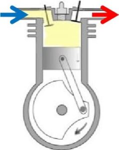
Reciprocating compressors function similarly to a car engine. A piston slides back and forth in a cylinder, which draws in and compresses the air, and then discharges it at a higher pressure. Reciprocating compressors are frequently multiple-stage systems, which means that one cylinder’s discharge will lead into the input side of the next cylinder. This allows for more compression than a single stage. Due to their relatively low cost, reciprocating compressors are probably the most commonly used compressors.

Rotary Screw

rrrrr
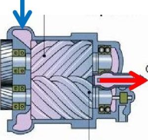
These compressors use two meshing screws (also called rotors) to compress the air. In oil flooded rotary screw compressors, lubricating oil bridges the space between the rotors. This provides a hydraulic seal and transfers mechanical energy between the driving rotor and the driven rotor. Air enters at the suction side, the meshing rotors force it through the compressor, and the compressed air exits at the end of the screws.

Rotary Sliding Vane

rot
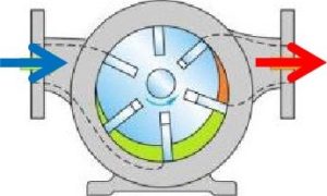
Rotary vane compressors consist of a rotor with a number of blades (vanes) inserted in radial slots in the rotor. The rotor is mounted offset in a housing. As the rotor turns, the blades slide in and out of the slots, keeping contact with the wall of the housing. Thus, a series of increasing and decreasing volumes are created by the rotating blades to compress the air. Centrifugal forces ensure that the vanes are always in close contact with the housing to form an effective seal.

Dynamic Compressors

Dynamic compressors use very high speed (up to 60,000 rpm) spinning blades or impellers to accelerate the air. The increased velocity causes an increase in air pressure. Dynamic Compressors deliver large volumes of air but generally at lower pressures. The following designs are the most common types of Dynamic Compressors:

Radial Centrifugal

radi
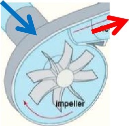
A rotating impeller in a shaped housing is used to force the air to the rim of the impeller, increasing the velocity of the air. A diffuser (divergent duct) section converts the velocity energy to pressure energy. Radial compressors are primarily used to compress air and gasses in stationary industrial applications.


Axial Flow

Ax
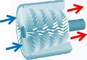
These compressors use fanlike airfoils (also known as blades or vanes) to compress air or gas. The airfoils are set in rows, usually as pairs, one rotating and one stationary. The rotating airfoils (rotors) accelerate the air. The stationary airfoils (stators) redirect the flow direction, preparing it for the rotor blades of the next stage. Axial compressors are normally used where very high flow rates are required. By nature of their design, axial flow compressors are almost always multi-stage.

The majority of compressors requires some form of lubrication to either cool, seal or minimize wear of their internal components. Many compressors are adequately lubricated by premium-grade turbine oils. We will address the specific lubrication requirements of the above compressors in more detail in the next issue of OilChat.

ACEA oil sequences 2016 update

ACEA oil sequences 2016 update OilChat#19

ACEA oil sequences 2016 update

Since the first ACEA (European Automobile Manufacturers’ Association) Oil Sequences were introduced in 1996, updated specifications were issued in 1998, 1999, 2002, 2004, 2007, 2008, 2010 and 2012- please refer to OilChat numbers 11 and 12. The long awaited next issue of the ACEA Oil sequences was finally released during December 2016. Reasons for this delay were the replacement of obsolete tests with new ones to reflect engine technology advancements and also to address the complications associated with the increase in use of biofuels.

The ACEA Oil sequence comprises of three classes: one for Petrol and Light Duty Diesel engines, one specifically for Petrol and Light Duty Diesel engines with exhaust after treatment devices and one for Heavy Duty Diesel engines. The ACEA sequences make up some of the industry’s most important performance standards and the ACEA 2016 update is a significant step for the global lubricant industry. ACEA 2016 sets a substantial increase in required performance from ACEA 2012.

ACEA 2016 Changes compared to ACEA 2012

The main features of the new ACEA 2016 engine oil sequences are the optimized performance capabilities in relation to the latest engine technologies, compatibility with new elastomer materials (seals, hoses etc.), improved compatibility with biofuels and increased potential to reduce fuel consumption. Some additional tests were also introduced for the individual categories.

ACEA 2016 Specific Changes

  • Category A1/B1 has been removed and not replaced.
  • Category C5 has been introduced to address the reduction of CO² levels and fuel consumption.
  • Introduction of various new engine tests:
  • CEC L-107 sludge test has not yet been finalized. In the interim Daimler’s sludge test is being used.
  • CEC L-111 petrol direct injection test for piston cleanliness and deposits in turbochargers.
  • CEC L-109 oxidation test for engine oils used with biodiesel.
  • CEC L-106 oil dispersion test at moderate temperatures for diesel direct fuel injection engines.
  • CEC L-112 test to check oil/elastomer capability.
  • CEC L-104 engine oil performance test to measure the effects of biodiesel using the DC OM646 DE22LA engine for piston cleanliness and sludge.

The ACEA 2016 Oil Sequence comprise the following twelve different Performance Categories within the three Service Classes:

A/B: Petrol and Light Duty Diesel Engine Oils (High SAPS)

A3/B3, A3/B4 & A5/B5

C: Catalyst Compatible Petrol and Light Duty Diesel Engine Oils (Low SAPS)

C1, C2, C3, C4, C5

E: Heavy Duty Diesel Engine Oils

E4, E6, E7, E9-

The table below summarises the changes that have occurred for each of the ACEA Oil Sequences since 1996:

ACEA 1996 ACEA 1998 ACEA 1999 ACEA 2002 ACEA 2004 ACEA 2007 ACEA 2008 ACEA 2010 ACEA 2012 ACEA 2016
A A1-96 A1-98 A1-98 A1-02
A2-96 A2-96 #2 A2-96 #2 A2-96 #3
A3-96 A3-98 A3-98 A3-02 A1/B1-04 A1/B1-04 A1/B1-08 A1/B1-10 A1/B1-12
A5-02 A3/B3-04 A3/B3-04 A3/B3-08 A3/B3-10 A1/B3-12 A3/B3-16
B B1-96 B1-98 B1-98 B1-02 A3/B4-04 A3/B4-04 A3/B4-08 A3/B4-10 A3/B4-12 A3/B4-16
B2-96 B2-98 B2-98 B2-98 #2 A5/B5-04 A5/B5-04 A5/B5-08 A5/B5-10 A5/B5-12 A5/B5-16
B3-96 B3-98 B3-98 B3-98 #2
B4-98 B4-98 B4-02
B5-02
C C1-04 C1-04 C1-08 C1-10 C1-12 C1-16
C2-04 C2-04 C2-08 C2-10 C2-12 C2-16
C3-04 C3-07 C3-08 C3-10 C3-12 C3-16
C4-07 C4-08 C4-10 C4-12 C4-16
C5-16
E E1-96 E1-96#2
E2-96 E2-96#2 E2-96#3 E2-96#3 E2-96#5 E2-96#5
E3-96 E3-96#2 E3-96#3 E3-96#3
E4-98 E4-99 E4-99 E4-99#3 E4-07 E4-08 E4-08#2 E4-12 E4-16
E5-99 E5-99
E6-04 E6-04#2 E6-08 E6-08#2 E6-12 E6-16
E7-04 E7-04#2 E7-08 E7-08#2 E7-12 E7-16
E9-08 E9-08#2 E9-12 E9-16

ACEA internationally omitted “E8” from the Sequences.


Each new issue of the Oil Sequences may include a new sequence, an increase in severity for an existing sequence or a change in testing with no change in severity. the nomenclature used by ACEA as a suffic to the Category, depends upon the type of change.

The complete ACEA 2016 Oil Sequences Requirements and Test Methods are available on http://www.acea.be/uploads/news documents/ACEA European oil sequences 2016.pdf

flash point

Flash Point of petroleum products OilChat#18

flash point

In this issue of OilChat we will endeavour to clear some of the fallacies surrounding Flash Point. It is often believed that the Flash Point of a volatile liquid is the temperature at which the liquid will ignite (start to burn) spontaneously without an ignition source. This however is not true. Flash Point is defined as the lowest temperature at which a liquid (usually a petroleum product) will form a vapour in the air near its surface that will “flash, ” or briefly ignite, on exposure to an open flame.

Flash Point is an indication of the flammability or combustibility of a substance. The lower the Flash Point, the greater the fire hazard. The use of the Flash Point as a measure of the hazardousness of petroleum products dates back to the 1 9th century. Before the advent of automobiles, paraffin was the most sought after petroleum product which was primarily used as fuel for lamps and stoves. At the time there was a tendency by petroleum distillers to leave as much as possible of the commercially ‘worthless’ petrol in the paraffin in order to produce more product. This adulteration of paraffin with highly volatile petrol caused numerous fires and explosions in storage tanks and household appliances. In response legal measures were instituted to curb the danger, test methods were prescribed and minimum flash points were set.

You may well wonder why we sometimes find a variance when we compare the Flash Points of two similar products. The answer lies in the test method used. Flash points are measured by heating a liquid to specific temperatures under controlled conditions and then applying a flame to the vapour above the surface of the liquid. The test is done in either an “open cup” or a “closed cup” apparatus.

In the open cup test the sample is poured into a test cup that is completely open at the top. A thermometer is placed in the sample before it is heated. The test flame is passed over the cup at every 2 0 C increase in the sample temperature. When the sample vapours ignite momentarily the Flash Point is reached. The most commonly used test method is the ASTM D92 Cleveland Open Cup (COC) test.

In the case of the closed cup test, the sample is placed in a test cup with a sealed lid that opens when the ignition source (flame) is applied. The closed cup traps all the vapours that are generated during the heating of the sample and the vapours are not exposed to the atmosphere as they are in the open cup method. It is therefore no surprise that the closed cup test yields lower Flash Points than the open cup test. The ASTM D93 Pensky-Martens Closed Cup (PMCC) test is normally used to determine closed cup Flash Points. There is no set conversion factor for these Flash Point tests but PMCC is generally 5 0 C to 1 SC lower than COC for lubricating oils.

Flash Point is often used as a descriptive characteristic of petroleum products, and it is also used to help portray the fire hazards of liquids. It refers to both flammable and combustible liquids. There are various standards for defining each term but it is generally agreed that:

  • liquids with a PMCC Flash Point less than 37.8 0 C are flammable, and
  • liquids with a PMCC Flash Point higher than 37.8 0 C are combustible.

Although Flash Point primarily characterizes the fire hazards of liquids, it can also be an indicator of the quality of the base oils used in lubricants. In days gone by Flash Point was not really an issue but since the introduction of lower viscosity oils, such as SAE 5W-40 and even SAE OW-30, it became a more important consideration. The thinner the oil, the lower the Flash Point and the greater the tendency for the oil to suffer vapourisation loss at elevated temperatures. This results in the oil to burn off on hot cylinder walls and pistons in engines and thereby increasing oil consumption. A PMCC Flash Point of 2000 C is generally recognised as the minimum Flash Point for engine oil to prevent possible increased oil consumption at high operating temperatures.

If the open cup test is continued at increased temperatures after the Flash Point is attained, a point may be reached where the vapour continues to burn after being ignited. When the sample vapour sustains combustion, the Fire Point is reached. The Fire Point of a liquid can therefore be defined as the lowest temperature at which the vapour continues to burn (for at least five seconds) after being ignited by an open flame. The Fire Point for petroleum products is seldom listed, while Flash Point appears on most product data sheets. Generally, the Fire Point is about 1 O O C higher than the Flash Point, but if the value must be known, it should be determined experimentally. It should be noted that Fire Point testing is not undertaken in closed cup apparatus.

What many people perceive to be the Flash Point is actually the Auto-Ignition Temperature. Unlike with Flash Point and Fire Point, the Auto-Ignition Temperature does not need an ignition source. The Auto-Ignition Temperature of a substance is the lowest temperature at which it will ignite spontaneously in a normal atmosphere without an external source of ignition, such as a flame or spark. The Auto-Ignition Temperature (also known as Kindling Point) is a much higher temperature than the Flash Point and Fire Point.

Q8 Petrol Station

Q8Oils and BCL sign lubricant agreement

Q8 Petrol Station

Leading automotive, industrial and energy solutions manufacturer Q8Oils – a subsidiary of oil giant Kuwait Petroleum Corporation – has signed a distribution and manufacturing license agreement with South Africa-based Blue Chip Lubricants Pty Limited. Based in Randburg, Blue Chip’s role as sole importer and distributor of Q8 lubricants in South Africa will also see the company manufacture locally to ensure they can deliver a high level of service and flexibility to their customers.

Commenting for Blue Chip, director Gary Marais says: “All products manufactured locally will be blended under strict Q8Oils quality controls, using its own high-quality base oils and additives. In addition, the formulations we use are the same as those used by Q8Oils customers in Europe and North America.”

Established in 1983, Blue Chip Lubricants is a leading independent manufacturer, marketer and distributor of a wide variety of high-quality lubricants and greases in South Africa; and has gained a reputation for the production of reliable products and services.

Championing the partnership, Q8Oils regional sales manager Abdulmohsen Homoud says: “When choosing a partner for this region it was essential that we found a high-quality blender and a ‘can do’ partner, both technically and commercially. The Q8Oils and Blue Chip partnership is a perfect fit for the South African market, with customers being the ultimate winners.”

He goes on to say that, with Q8Oils’ marketing, manufacturing and research headquarters remaining in Europe, Blue Chip has significant corporate resources to call on whenever they are required.

tractors working

Universal tractor lubricants OilChat#17

tractor

This is not an optical illusion.

Tractors don’t come up on our radar screens all that often but modern farm equipment is a far cry from the “mechanical plow horses” of yesteryear. These new machines may still not break any speed record, but space technology is now being incorporated into agricultural equipment in the form of GPS devices, onboard computers, auto-steer system and even driverless technology!

Notwithstanding this array of state-of-the-art gizmos, lubrication still plays a critical role in the efficient and reliable operation of agricultural machinery. Tractors and other farm equipment, such as combined harvesters, have various components that need to be lubricated. These include the engine, transmission, final drives, oil immersed ( wet ) brakes hydraulic system and the power take-off ( PTO ). Just imagine the cost consequences if farmers had to stock different oils for all these applications. Furthermore, with so many lubricants in the oil store, there is also the risk of using the wrong oil for a specific component. It is therefore no wonder that agricultural equipment manufacturers and oil companies have worked together to come up with multifunctional lubricants:

Super Tractor Oil Universal (STOU/SUTO)

These oils fulfill several roles and make machine maintenance much simpler. They also reduce the number of lubricants farmers need to keep around because they can generally be used for all the applications mentioned above. When you peruse the product data sheet of a reputable STOU you will find that it meets the requirements of a host of Industry and Equipment Manufacturers’ (OEM) specifications. These may include, but are not limited to, the following:

  • Engines: API CG-4/SF
  • Gears: AP GL-4
  • Transmissions: ZF TE-ML 06A / 06B / 06C / 06G
  • Wet Brakes: Case MS 1317
  • Hydraulics: Eaton Vickers M-2950-S.

A STOU fluid can be described as a general-purpose farm lubricant with reasonable engine performance, fair load carrying capacity for gears and moderate hydraulic oil performance. However, as engines become more demanding, transmissions more sophisticated and hydraulic system pressures higher, trying to meet all the requirements with one fluid becomes more complicated. For instance, if a manufacturer recommends an API CI-4 performance level oil for the engine, two separate lubricants may have to be used since it is unrealistic to expect a single oil to meet API CI-4 and all the other service categories mentioned above. In such an instance it would be advisable to use a dedicated engine oil and a higher performance multifunctional lubricant for the other components.

Universal Tractor Transmission Oil ( UTTO )

These lubricants are also referred to as Tractor Hydraulic Fluid ( THF ) or Transmission, Differential and Hydraulic ( TDH ) fluid. They are used where the equipment manufacturer recommends a separate engine oil. UTTOshave no engine oil credentials, better hydraulic oil performance and improved wet brake fluid characteristics.

When you compare STOU and UTTO product data sheets you may well find they have some transmission, rear axle, wet brake and hydraulic oil specifications in common. However high-performance UTTOs will boast with OEM specifications that are unlikely to be met by STOUs such as:

  • Case MS 1207: Hy-Tran Plus, transmissions, hydraulics, wet brakes
  • Massey Ferguson CMS M 1141: Transmissions, hydraulics, highly loaded wet brakes
  • Volvo 97302-10: Transmission with built in wet brakes

As tractors become more sophisticated and require higher quality oils for satisfactory performance, there will most likely be an increased trend away from the all-purpose STOU fluid to a specific engine oil and UTTO combination.

TO-4 Fluid

UTTOs should not be confused with TO-4 fluids. UTTOs are mainly used in agricultural applications, although they are sometimes recommended for construction machines, such as Bell ATDs. TO-4 fluid originates from the Caterpillar TO-4 ‘Transmission Oil’ specification. TO-4 has become a standard term used within the industry for a specific type of additive/ fluid. TO-4 fluids normally meet Allison C4and other OEMrequirements as well.

Although both UTTOs and TO-4 fluids are designed for wet brake applications, they are not interchangeable since they have different frictional properties.Construction machinery, for which TO-4 fluids are intended, is normally much bigger and heavier than agricultural equipment. A higher level of friction is required to ensure that these heavy machines can stop on steep slopes, such as access roads down open cast mines.Tractor size, and therefore weight, is limited, as they need to use public roads, and therefore less friction is required to stop agricultural equipment. This results in TO-4 fluids having a higher coefficient of friction than UTTOs. Using the wrong fluid will mean that fluid/brake surface interaction will be affected and thereby reducing braking efficiency with possible catastrophic results.

Conclusion

Know your equipment manufacturer’s recommended lubricants, have them on hand and pay attention to tractor and equipment service intervals. If in doubt our experts are at your disposal, ready to provide you with advice and to answer any of your questions. For more information, please visit www.bcl.q8oils.co.za

drive shaft

Lubricating grease part 2 OilChat#16

drive shaft

Grease consists of a liquid lubricant that is mixed with a thickener ( see OilChat #15 ). Additives imparting special properties may also be included. Although is is liquid lubricant ( and certain additives) in the grease that provides the necessary lubrication, grease and oil are not interchangeable in their applications. The combination of the thickener, fluid and additives incorporated in grease produce certain properties or characteristics that grease does not share with lubricating oil.

The characteristics most commonly considered when selecting grease for a specific application included, but are not limited to the following:

Consistency is a key property of grease and is a measure of the relative hardness of the grease. Consistency is measured using a “penetrometer”. A cone is released and allowed to sink into the grease, under its own weight, for 5 seconds. The depth that the cone has penetrated into the grease is then read in tenths of a millimeter. The further the cone penetrates the grease, the higher the penetration result and the softer the grease. The National Lubricating Grease Institute (NLGI) has established consistency numbers ranging from 000 to 6, corresponding to specified ranges of penetration numbers. The table below lists the NLGI grease classifications along with a description of the consistency and how it relates to common foods:

[wpsm_comparison_table id=”7″ class=””]

NLGI 2 grease is the most common consistency used globally

Dropping Point is indicative of the heat resistance of grease. The Dropping Point is the temperature at which grease becomes fluid enough to drip under controlled conditions in a laboratory test. In general, the dropping point is the temperature at which the grease passes from a semisolid to a liquid state. This change is irreversible in greases containing conventional soap thickeners. Greases with materials other than conventional soap thickeners can, without a change in state, separate oil. The dropping point indicates the upper-temperature limit at which a grease retains its structure and NOT the maximum temperature at which a grease may be used. A good rule of thumb is to consider the dropping point minus 50°C as the maximum useful temperature limit.

Oxidation Stability is the ability of grease to resist breakdown in reaction with oxygen at elevated temperatures. Although both the base oil and thickener can oxidize, oxidation is more of a danger to the base oil. Oxidation turns grease into a sludge and causes gummy deposits to form on machine and component surfaces. Oxidized grease will become softer and appear darker. Prolonged exposure to excessive temperatures accelerates oxidation and can even result in carbonization where grease hardens or forms an abrasive black crust.

Structural Stability is a vital performance characteristic of lubricating grease as it is a measure of how the grease consistency will change in service when it is subjected to shear as a result of movement. Grease softening in a bearing may cause the grease are developed through careful selection of the thickness composition and effective manufacturing process.

Water Resistance is the ability of grease ti withstand the effects of water with no or little change in its ability to lubricate. Water can affect the grease stability resulting in hardening of softening. A drop inconsistency can cause the grease to be washed away from the bearing. In some instances, grease may also absorb the water and suspend the oil in the grease forming an emulsion that can reduce lubricity by diluting and changing grease consistency and texture. In extreme case water can displace the oil completely, causing the oil to leak away. In order to maintain its structure, the grease is required t have good water repellence in addition to adequate water tolerance properties.

Pumpability is an indication of how easily pressurized grease will flow through lines, nozzles, and fitting of grease dispensing system. Good pump ability characteristics are particularly important at low operating temperatures or when grease is used in automatic lubrication system where the grease is pumped through long lines from a central reservoir. If the temperature of grease is lowered sufficiently, It will become to viscous to flow and machine operation will be impossible. It is therefore important to check the recommended usable temperature range on the product data sheet when considering grease for arduous climatic condition.

Load Carrying Capacity is defined by the American Society for Testing and Material ( ASTM ) as the maximum load or pressure that can be sustained by a lubricating grease without failure of the sliding contact surfaces. In some circumstances the lubricating oil in the grease will prevent the breakdown of the lubricating fluid film under load, and only the action of anti-wear or extreme pressure (EP) additives in the grease will prevent surface contact and wear. in test to evaluate the load carrying capacty of grease, high loads are applied to moving surfaces that are in contact and lubricated by the grease. There are many test for determining the load carrying ability of grease, but the most commonly used ones are the Timken OK Load test and the Four Ball Weld/ Load Wear Index test.

When selecting grease fo a particular application all of these properties need to be compared to the requirenebts of the application. It could be disastrous to choose a grease based on NLGI grade only. The completed package of grease characteristics, including the fluid component viscosity, must be considered in order to choose the best grease for the job.

Important to remember is that all grease are not compatibile. It is therefore recommended that when changing from one grease to another, all the old grease should be cleaned out before the new grease is applied.